Selasa, 28 April 2015

1999-2003 FORD SUPER DUTY F SERIES HIGH PRESSURE OIL PUMP LEAK

http://ww2.justanswer.com/uploads/jmcdo28/2009-10-27_012423_tsb04-04-04.pdf
1999-2003 FORD SUPER DUTY F SERIES HIGH PRESSURE OIL PUMP LEAK - FORD: 1998-2003 E SERIES 1999-2003 SUPER DUTY F SERIES 2000-2003 EXCURSION, F-650, F-750 This article supersedes TSB 03-21-50 to update the WARNING service procedure and illustration. DO NOT REMOVE OR ATTEMPT TO REPAIR A LEAK AT THE PLUG PICTURED IN LOWER LEFT ISSUE CORNER OF FIGURE 1, OR DAMAGE TO THE Some 1998-2003 E-Series, 1999-2003 Super Duty, PUMP WILL RESULT. 2000-2003 Excursion, and 2000-2003 F650/750 1998-2003 E-SERIES HIGH PRESSURE OIL vehicles equipped with a 7.3L Diesel engine may PUMP ACCESS PROCEDURE (DISASSEMBLY) exhibit an oil leak at the high pressure oil pump outlet fittings and/or end plug (see Figure 1).

The 1. Remove the Intake Air Resonator. For leak may appear to be a rear main crankshaft seal, additional information, refer to Section 303-12 in oil pan gasket, or other engine oil leak due to the the appropriate Workshop Manual. drain hole machined in the crankcase valley which allows any oil in the valley to run down the back of 2. Remove the exhaust back pressure sensor. the engine. a.

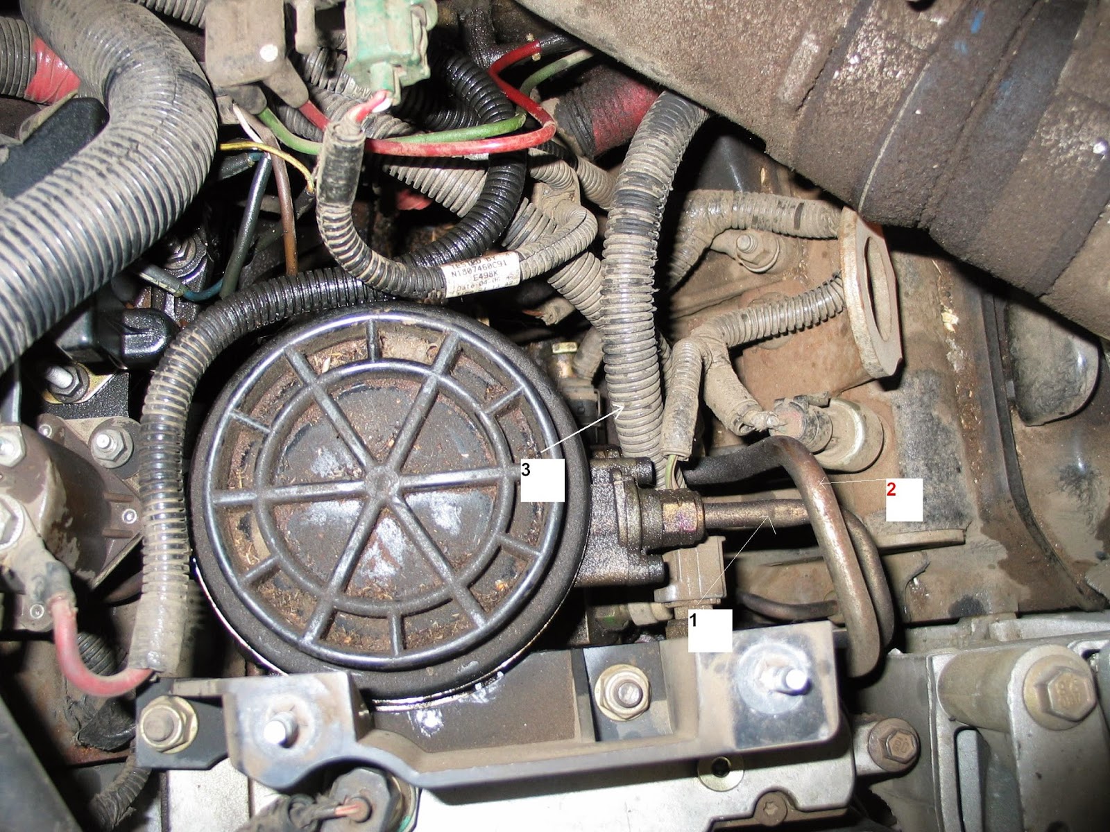
Disconnect the exhaust back pressure ACTION sensor electrical connector. High pressure oil pump leaks at the outlet fittings b. Remove the exhaust back pressure sensor. and/or end plug can be serviced without removing the pump assembly. Replace the O-rings on the 3. Remove the high pressure oil pump reservoir. fittings and the end plug using Kit 2C3Z-9G804-AA. For additional information, refer to Section All three (3) O-rings should be replaced. Apply 303-04 in the appropriate Workshop Manual. liquid thread sealer (included in the kit) prior to WARNING reinstallation.

Refer to the following Service Procedure for details. 4. Open the fuel/water separator drain valve to FOLLOW THE PROPER HIGH PRESSURE OIL release fuel pressure. Completely drain the fuel PUMP ACCESS PROCEDURE IN THIS filter/water separator assembly. DOCUMENT FOR ACCESS TO THE HIGH 5. Disconnect the fuel supply and fuel return lines PRESSURE OIL PUMP. from the fuel filter/water separator. NOTE 6. Disconnect the two (2) cylinder head fuel FOR SUPER DUTY AND EXCURSION, PROCEED supply lines from the fuel filter/water separator. TO O-RING SEAL REPLACEMENT PROCEDURE.

Download : 1999-2003 FORD SUPER DUTY F SERIES HIGH PRESSURE OIL PUMP LEAK

Test Guidelines for Use of Essential Tool J 41413-200 Evaporative System Tester

Test Guidelines for Use of Essential Tool J 41413-200 Evaporative System Tester - Models: 2002 and Prior Passenger Cars and Light Duty Trucks with Non-Enhanced and Enhanced EVAP Systems. Non-Enhanced EVAP System Diagnostic Procedure 1. Pinch off or plug the EVAP vapor line to seal the EVAP system. 2. Connect the EEST red battery clip to the positive (+) battery terminal.

Connect the black battery clip to chassis ground. 3. Install the appropriate fuel fill cap adapter to the fuel fill pipe. Refer to the Service Information for the appropriate fuel fill cap adapter part number. 4. Connect the EEST’s nitrogen/smoke supply hose and vehicle fuel fill cap to the adapter. 5. Turn the nitrogen/smoke valve on the EEST control panel to SMOKE. 6. Use the remote switch to introduce smoke into the EVAP system for 60 seconds.

 Important: Additional smoke may need to be introduced at 15-second intervals until the leak source has been located. 7. Inspect the entire EVAP system for exiting smoke using the high intensity white light (J 41413-SPT). Enhanced EVAP System Leak Detection Procedure When diagnosing DTCs P0440, P0442, P0446 and P0455, use the J 41413-200 EEST along with Subject: Test Guidelines for Use of Essential Tool J 41413-200 Evaporative System Tester Models: 2002 and Prior Passenger Cars and Light Duty Trucks with Non-Enhanced and Enhanced EVAP Systems the following procedure anytime the diagnostic calls for the J 41413 EVAP Pressure/Purge Diagnostic Station. Important: ENSURE THAT THE VEHICLE UNDERBODY TEMPERATURE IS SIMILAR TO THE AMBIENT TEMPERATURE AND ALLOW THE SURROUNDING AIR TO STABILIZE BEFORE STARTING THE DIAGNOSTIC PROCEDURE. 1. Turn ON the ignition with the engine OFF. 2. Command the EVAP vent valve closed with a scan tool.* *Prizm: In order to seal the EVAP system on the 1998-2002 Prizm, bypass the EVAP canister by connecting the fuel tank vapor hose to the canister purge line. Refer to the Service Information for additional information. 3. Connect the EEST red battery clip to the positive (+) battery terminal.

Connect the black battery clip to chassis ground. 4. Install the appropriate fuel fill cap adapter to the fuel fill pipe. Refer to the Service Information for the appropriate fuel fill cap adapter part number. 5. Connect the EEST’s nitrogen/smoke supply hose and vehicle fuel fill cap to the adapter. 6. Turn the nitrogen/smoke valve on the EEST control panel to SMOKE. 7. Use the remote switch to introduce smoke into the EVAP system. 8. Use the J 41413-VLV EVAP Port Vent Fitting tool to open the EVAP service port (if equipped) until smoke is observed.
Download : Test Guidelines for Use of Essential Tool J 41413-200 Evaporative System Tester

Popular Posts

Twitter Facebook More

 
Design by Free WordPress Themes | Bloggerized by Lasantha - Premium Blogger Themes | Affiliate Network Reviews