Tampilkan postingan dengan label Acura. Tampilkan semua postingan

Senin, 11 Mei 2015

1998 Acura 3.5RL ENGINE PERFORMANCE Basic Diagnostic Procedures

1998 Acura 3.5RL ENGINE PERFORMANCE Basic Diagnostic Procedures - 1. Remove fuel tank filler cap. Listen for fuel pump operation noise at fuel tank filler. Fuel pump should operate for 2 seconds after ignition switch is turned on. If fuel pump operates as specified, fuel pump is okay. If fuel pump does not operate as specified, go to next step. 2. Turn ignition switch off. Remove rear seat or trunk floor to gain access to fuel pump connector. Disconnect fuel pump connector. Disconnect PGM-FI main relay connector. Connect a fused jumper wire between PGM-FI main relay connector FUEL PUMP fuse side terminal and fuel pump side terminal. See L – WIRING DIAGRAMS article. 3. Turn ignition switch on. Using a voltmeter connected to ground, check for battery voltage at fuel pump harness side connector. See L – WIRING DIAGRAMS article. If battery voltage is not present, check harness between fuel pump and FUEL PUMP fuse. Repair as necessary. If battery voltage is present, check fuel pump ground.

Repair as necessary. If ground is okay, replace fuel pump. PGM-FI MAIN RELAY Integra, 2.3CL, 2.5TL & 3.0CL 1. Remove PGM-FI relay, located under left side of instrument panel. Connect battery voltage to relay terminal No. 2. Connect terminal No. 1 to ground. See Fig. 1 . 2. Test for continuity between relay terminals No. 4 and 5. If continuity exists, go to next step. If continuity does not exist, replace relay. 3. Connect battery voltage to relay terminal No. 5. Connect terminal No. 3 to ground. Test for continuity between relay terminals No. 6 and 7. If continuity exists, go to next step. If continuity does not exist, replace relay. 4. Connect battery voltage to terminal No. 6. Connect terminal No. 1 to ground. Test for continuity between relay terminals No. 4 and 5. If continuity exists, relay is okay.

If continuity does not exist, replace relay. 1. Remove PGM-FI main relay located under left side of instrument panel. Connect battery voltage to relay terminal No. 4. Connect terminal No. 8 to ground. See Fig. 2 . 2. Test for continuity between relay terminals No. 5 and 7. If continuity exists, go to next step. If continuity does not exist, replace relay. 3. Connect battery voltage to relay terminal No. 6. Connect terminal No. 2 to ground. Test for continuity between relay terminals No. 1 and 3. If continuity exists, go to next step. If continuity does not exist, replace relay. 4. Connect battery voltage to relay terminal No. 3. Connect terminal No. 8 to ground. Test for continuity between relay terminals No. 5 and 7. If continuity exists, relay is okay. If continuity does not exist, replace relay.

Download : 1998 Acura 3.5RL ENGINE PERFORMANCE Basic Diagnostic Procedures

Senin, 04 Mei 2015

Honda/Acura Nitrous Oxide Injection System Manual Installation Instructions

Honda/Acura Nitrous Oxide Injection System Manual Installation Instructions - System Requirements When used correctly, Kit Number 08201NOS is designed to work with stock Honda internal engine and driveline components. The jet combination in this kit generates a 50 HP gain at the flywheel. If the jetting is increased over 50 HP, it is advised to upgrade the fuel delivery system, retard timing, and use a colder spark plug to ensure safe operation. Higher HP levels also require additional modifications, such as forged pistons.

Chapter 2 Kit Installation 2.1 Bottle Mounting Instructions Accurate calibration of your NOS nitrous system depends on the bottle remaining at a stable temperature. Mount the bottle away from heat sources, such as the engine compartment or exhaust system, and away from windows, where the bottle is exposed to direct sunlight. 2.2 Bottle Orientation Bottle placement is critical to the performance of your NOS nitrous system. It is important to understand how the bottle valve and siphon tube are assembled to properly orient the bottle in your vehicle and ensure that it picks up liquid nitrous while undergoing acceleration. All nitrous bottles are assembled so that the bottom of the siphon tube is at the bottom of the bottle and opposite the bottle label (Figure 2). Whenever the bottle is mounted in a lay-down position, the valve handle must be towards the front of the vehicle with the label facing up (Figure 3A).

2.3 Bottle Installation Before mounting a nitrous bottle in a racing vehicle intended for use in sanctioned events, check with the sanctioning association for any rules regarding this subject. Most associations require the bottle to be mounted within the confines of the safety roll cage with the safety pressure relief cap vented away from the driver’s compartment. This feature is included in the 08201NOS kit. NOTE: Numbers in parentheses ( ) refer to the parts list (Table 1). 1. Install the bottle nut adapter (1) and washer (2) on the nitrous bottle (3), and tighten securely. 2. Slip the bottle mounting brackets (4 & 5) onto the nitrous bottle, as shown in Figure 3E. 3. Locate the bottle assembly in the desired mounting location, ensuring that the location will provide easy access to the bottle valve, hose connection, bracket clamp bolts to facilitate bottle changing and through hole of the blowdown tube. 4. Use the assembled bottle/bracket unit as a pattern to mark for hole drilling. Drill four 11/32″ holes in the mounting surface for the bottle bracket bolts. Make sure the holes are in a position that does not damage other components.

Download : Honda/Acura Nitrous Oxide Injection System Manual Installation Instructions

Sabtu, 02 Mei 2015

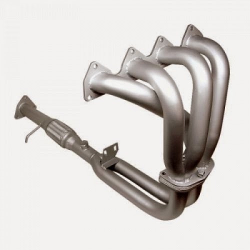
Acura Integra Header Installation Instructions


Acura Integra Header Installation Instructions - Parts List: 1 – Stainless Steel Header 1 – Oxygen Sensor Plug (for cars with oxygen sensor in catalytic converter) • Remove existing exhaust manifold and “A” pipe: Remove manifold, “A” pipe, and heat shields per factory service manual removal procedures. • Loosen bracket: Loosen the bracket indicated in the diagram to the right. This will allow easier alignment of the header to this bracket. • Install oxygen sensor: Install oxygen sensor into bung on collec- tor. Note: Some cars will have the oxygen sensor in the catalytic converter. In this case, install the supplied plug into the fitting on the header collector. • Install Comptech Header: Install header from bottom of car, line up all connections, and start all nut and bolt fasteners before final tightening to factory specifications. (torque header to cylinder head bolts/nuts to 23 lbs/ft) see diagram at right for other torque specs. • Wipe down header: Use a good solvent to remove any oil or contaminants on the header before starting engine. This will insure even discoloration (typical of stainless steel) of the header as it heats up. • Start engine: Start the engine and check for any exhaust leaks. After a few days of driving the car, recheck all con- nections for tightness.

Download : Acura Integra Header Installation Instructions

1990-1993 Acura Integra Radio Replacement

http://carmarzus.blogspot.com/
1990-1993 Acura Integra Radio Replacement - Remove Factory Radio NOTE : To remove the Honda factory radio, (2) two screws at the rear of the radio must be removed from underneath the radio which can be accessed from behind the radio. The Honda radio is secured to the pocket below the radio and will pull out of the dash connected together as one unit. STEP 1 : Move to the passenger side of the vehicle. The screws that secure the radio/pocket assembly to the dash are at the rear of the radio.

The only way to access these screws is to look up at the rear of the radio from the passenger side of the vehicle. With an 8mm socket or phillips screw, locate and remove the screws as can be seen in the photos shown in the NOTE to the left. STEP 2 : Once the screws at the rear of the radio/ pocket assembly have been removed, the radio can be pulled forward out of the dash. Remove Factory Radio STEP 3 : Pull the radio out of the dash. Unplug the black cable plugged into the rear of the radio. Unplug the white plastic wire harness connector plugged into the rear of the radio. Completing The Radio Installation Move to: Wire New Radio Section Wiring The New Radio STEP 1 : Insert the radio installation kit into the dash until it snaps and secures to the dash. TIP: mount the kit to the opening in the dash BEFORE mounting the radio to the kit.

Mounting the radio to the kit before snapping the kit into the dash may prevent the kit from properly snapping into the dash. This step is shown in more detail in the “Mount New Radio” section. STEP 2 : Insert the new radio into the dash. Plug the black antenna cable into the rear of the new radio. Make sure all wire connections for the new radio have been completed and plug in any connectors for the new radio now. Slide the new radio into the radios mounting “cage” or mounting “sleeve”. The Installation Is Now Complete.
Download : 1990-1993 Acura Integra Radio Replacement

Jumat, 01 Mei 2015

Acura RSX Heated Mirror Installation Instructions

Acura RSX Heated Mirror Installation Instructions - Dissassembly: OK so let’s get started: It’s best if you have the Helms manual but you can do without it if you have done other similar installs on this or other cars. 2. Remove the door panel: a. You will need to remove the door handle assembly. Pop off the plastic cover behind the handle and you will find 2 screws.

Once you undo the screws you can pull the assembly out. Remove the lock cable from the door handle. b. Then unplug the connector. There is one more screw you will need to find once you remove the handle assembly. Remove this screw too. Every time I did this, the screw fell into the plastic door panel handle cavity so I had to retrieve this screw after the door panel came off by turning the panel upside down. Next remove the 2 screws under the armrest. c. Remove the black plastic trim piece on the inside of the door opposite the mirror. Roll the window down and pop the piece up and inward using a little upward pressure. A screwdriver taped so it would not mark or scratch anything works best. d. Now you are ready to remove the door panel.


To do this it is best to use a door trim tool. You can pick one up at your local auto store. This is used to remove the 8 clips that hold the plastic panel to the sheet metal. e. In order to completely remove the panel, unplug the connector for the window switch. 3. Remove the mirror assembly: Note it is possible to skip this step and work on the mirror while attached to the car a. Unscrew the three 8 mm nuts holding the mirror to the inside of the window. b. Unplug the mirror connector and take the mirror assembly totally off 4. Remove the glass mirror element from the assembly: a. Gently push the top of the mirror in as far as it will go. This will create a small space between the bottom of the mirror and the housing. Use mostly just your fingers for this.

 I also used a hair dryer and an assistant to heat the mirror (don’t over do it) while pulling the mirror with the black plastic holder from the white plastic actuator. I did use a screwdriver here very delicately to help separate the two items. This was easily accomplished without breaking the old mirror.

Download : Acura RSX Heated Mirror Installation Instructions

Popular Posts

Twitter Facebook More

 
Design by Free WordPress Themes | Bloggerized by Lasantha - Premium Blogger Themes | Affiliate Network Reviews