Tampilkan postingan dengan label Ford. Tampilkan semua postingan

Selasa, 12 Mei 2015

Ford C-4 Bracket and Lever Installation Instructions


Ford C-4 Bracket and Lever Installation Instructions - STEP 1. Raise and safely support the vehicle at least 1-2 feet off the ground. Remove the nut and lock- washer holding the downshift linkage onto the downshift lever shaft. The downshift lever is the outer lever on C-4 transmissions. Pull the lever off the shaft and allow the linkage to hang free. Remove and discard stock shift linkage rods. Late C-4 transmissions have a Neutral safety/Backup light switch on the transmission shift lever. If your transmission is so equipped, remove the two bolts holding the switch in place and slide it off the shift shaft. Disconnect the switch at the factory plug and discard it. STEP 2. Install the B&M selector lever, See figure 1 . Note: The B&M lever must point downward for proper operation. If the stock shift lever on your transmission points down, you will have to remove the lower part of the stock arm by cutting it off to clear the B&M lever, (See figure 1 ) . Install B&M selector lever onto shift shaft of transmission. Align selector lever so when it points straight down it travels equal arcs in both directions from center, then tighten 1/4″-20 x 1 1/2″ pinch bolt and nut. The lever should travel smoothly from front to back with a positive click in each gear position. Make sure O-ring is in position on downshift shaft and install downshift. lever in position on shaft. Install lockwasher and nut and tighten securely. Downshift lever must operate smoothly.

Reconnect downshift linkage. STEP 3. Remove the two lower bolts from the rear servo cover. Install cable bracket in position, (See figure 1 ). Install two servo cover bolts as removed and tighten 12-13 ft. lbs. Do not overtighten as this can distort servo cover. STEP 4. Route the shifter cable according to figure 2 Avoid kinks and sharp bends and route the cable away from hot engine or exhaust parts. Remove the two rubber boots, one large nut, and a large lock- washer from the threaded end of the shifter cable. Slide the end of the cable into the cable bracket, Install large nut and lockwasher loosely over end of cable. Install two rubber boots onto end of cable. Install the swivel on the threaded end of the cable and position it in the center of the threaded portion. STEP 5. Move the transmission selector lever by hand to full rear position (LOW). Place the shifter lever to the low gear position (ratcheted all the way back). Adjust the large nuts on the cable so that the swivel will slide into the hole on the selector lever. Tighten the large nuts completely. Be sure that the swivel will slide freely in and out of the hole in the selector lever.

Download :  Ford C-4 Bracket and Lever Installation Instructions

1998 FORD Ranger 4.0L OHV UPPER ENGINE GASKETS REPLACING INSTRUCTIONS

1998 FORD Ranger 4.0L OHV UPPER ENGINE GASKETS REPLACING INSTRUCTIONS -
Ford 4.0L (OHV) Upper Intake Manifold Assembly Removal & Installation Removal 1. Disconnect the battery ground cable. 2. I highly recommend taking the hood off. Mark where the bolts connect on the hood to ensure proper alignment upon re-installation. My trick was to use “white-out” to do this, comes with a nice little brush. 3. Remove the air cleaner outlet tube by loosening the clamp next to the MAF and the clamp next to the Throttle Body. 4. Disconnect the accelerator cable from the throttle body arm, and then unclip the accelerator cable from the speed control actuator cable. Move them out of the way. 5. Disconnect the vacuum hoses from the brake vacuum booster, EGR valve and crankcase ventilation hose.

 6. Disconnect the wiring harness connectors from the EGR valve, the DPFE sensor, and the idle air control (IAC) valve. 7. Disconnect the DPFE sensor hoses. 8. Disconnect the throttle position sensor (TPS) harness connector. 9. Disconnect the throttle body vapor management hose. This is the small coolant hose that runs directly to a port on the bottom of the TB. 10. Disconnect the spark plug wires from the ignition coil. 11. Disconnect the harness connector from the ignition coil and the radio ignition interference capacitor. 12. Slide the engine sensor control connector off the bracket. This is the large black connector that is located up near the firewall on the driver’s side of the engine bay. 13. Remove all 6 nuts (13mm) holding down the upper intake manifold, and the small attached bracket. 14. Remove the upper intake manifold assembly by pulling straight up. 15. Remove the upper intake manifold gaskets from the upper intake.

Installation 1. Installation of the Upper Intake Manifold Assembly is the reverse of removal. Tighten the nuts in the sequence shown: Ford 4.0L (OHV) Valve Covers & Gaskets – Removal & Installation Removal 1. Remove the upper intake manifold as described above. 2. Disconnect the vacuum line that goes into the top of the EGR valve. 3. Remove the bolts (10 mm) securing the EGR valve to the Tube that goes into the upper intake. 4. Remove the oil level indicator tube. 5. Remove the EGR Tube and the bracket (Be careful not to let the metal gasket fall and get lost). 6. Remove the valve cover bolts (10 mm). 7. Remove the valve covers (requires some lifting and twisting) and the valve cover gaskets. Installation 1. Clean and inspect the gasket sealing surfaces.

Download : 1998 FORD Ranger 4.0L OHV UPPER ENGINE GASKETS REPLACING INSTRUCTIONS

Senin, 11 Mei 2015

2008-2011 FORD Focus PART 99-5816 INSTALLATION INSTRUCTIONS

2008-2011 FORD Focus PART 99-5816 INSTALLATION INSTRUCTIONS - KIT FEATURES • DIN Radio Provision with Pocket • ISO Mount Radio Provision with Pocket • Double DIN Radio Provision • Stacked ISO Mount Units Provision • Painted To Match Factory Dash • A) Radio Housing • B) ISO Brackets • C) ISO Trim Plate • D) Double DIN Brackets • E) Double DIN Trim Plate • F) Pocket • G) (2) Top Clips and (4) Middle Radio Housing Clips Wiring & Antenna Connections (sold seperately) XSVI-5520-NAV – Ford Interface AFSI-02 – if equipped w/ sync 70-5522 – Ford Sub Harness KIT COMPONENTS A TOOLS REQUIRED: Small Flat Blade Screwdriver/ Panel Removal Tool • Phillips Screwdriver • Socket Set • Cutting Tool. 95-5816 DASH DISASSEMBLY. to prevent an accidental short cir- cuit. 1 Unclip and remove the trim panel surrounding the shifter and including the cup holders. (Figure A) Remove (2) 9/32″ screws facing up above the gauge cluster then unclip and remove the trim panel surrounding the gauge cluster. (Figure C) Unclip and remove the trim panel above the glove box.

(Figure D) top of the factory radio trim panel. (Figure E) 6 Remove (4) T-20 Torx screws securing the climate controls to the factory radio trim panel assembly and remove the controls from the assembly. (Retain the screws and climate controls for re-use during kit preparation.) (Figure G) 9 Remove (4) T-20 Torx screws securing the accessory socket panel to the factory radio trim panel assembly and remove the socket panel from the assembly. (Retain the screws and accessory socket panel for re-use during kit preparation.) (Figure G) 10 Unclip and remove the passenger air bag light and the switch panel blank plates. (Retain the air bag light and blank plates for re-use during kit preparation.) (Figure G) 11 Unclip the factory radio trim panel assembly. Unplug and remove the assembly. Note: Some early models had a ground strap attached to the radio chassis and the sub dash with an 8 MM bolt. You will need to unbolt this strap to remove the factory radio trim panel assembly.

Download : 2008-2011 FORD Focus PART 99-5816 INSTALLATION INSTRUCTIONS

Minggu, 10 Mei 2015

1937 Ford Tail lights Installation Instructions


1937 Ford Tail lights Installation Instructions - 1. Disconnect Battery . Do not skip this step . Also, do not try to “test” the LED array by connecting the leads directly to your battery. Permanent damage will occur to the LED array if you fail to heed these steps. 2. Remove taillight lens and bezel. 3. Remove light bulb and light bulb holder. 4. Remove the LED array from the stainless steel bracket. 5. Route the supplied electrical harness through the taillight and to the area where connections will be made. 6. Install the stainless steel bracket in the taillight housing using the supplied screw.

Also attach the green ground wire from the supplied harness to this screw. 7. Attach the plastic connector on the supplied harness to the LED array. 8. Deform the supplied plastic spacers to hold them on the screw during installation. 9. Align the LED array and stainless steel bracket while installing the supplied stainless steel screws and lockwashers. 10. Reassemble the rest of the taillight. 11. Wiring . Using the supplied connectors, connect the wire from the taillight circuit to the black wire on the supplied harness. To use the connector: 12. Repeat by connecting the wire from the brake light circuit on your car to the red wire on the supplied harness. If your car is fiberglass, the housing must be grounded. 13. Repeat for the other side. 14. Reconnect the battery. 15. Test both STOP and taillight functions. 16. Enjoy! Photo Explanation

1. Disassemble the LED array from its bracket and install the bracket using the supplied screw. 2. Route the electrical harness. Note the location of the green ground wire. 3. Plug the green harness connector into the receptacle on the LED array. 4. Deform the plastic spacers to hold them in place during assembly. 5. Install the LED array. 6. Parts included in the Technostalgia kit. Technical Notes 1. For cars using the stock license plate location, the LED will not illuminate the license plate. We suggest using the commercially available LED license plate bolts.

Download : 1937 Ford Tail lights Installation Instructions

MONSTER TRANSMISSIONS : FORD TRANSMISSION INSTALLATION INSTRUCTIONS


MONSTER TRANSMISSIONS : FORD TRANSMISSION INSTALLATION INSTRUCTIONS - Please Note : The following instructions were made to act as a guide/reference, if you are inexperienced with performing an automatic transmission installation it is highly recommended that you contact a certified experienced professional to perform the installation and/or make the proper adjustments for you! Instructions : (1) Pre-installation instructions; Disconnect Battery terminal, inspect and check transmission coolant lines for damage, flush lines and coolant system thoroughly. (2) Inspect crank well for converter hub wear, and clean this area. (3) Check Flywheel for cracks and converter bolt holes for wear. (4) Inspect back of engine block where transmission mates, ensure block is clean, no wires or cables are in the way of installation. (5) Inspect and verify both dowel pins are clean and secure in block. (6) Ensure Block Plate is aligned and straight. (7) Clean area of block so transmission can make a good ground. “Warning” Transmission will suffer permanent damage if grounded improperly!

Installation : (1) Transmission Fluid: you need about 10 to 12 quarts of fluid for installation, Dextron III with Mercon, 1968 – 1993 Vehicles and Mercon 5, 1994 and Newer, any brand name. (2) If transmission was purchased with a torque converter from Monster Transmission & Performance, no need to follow step (3). (3) Add (1) quart of transmission fluid to converter prior to installation of transmission. (4) Install Converter on transmission carefully; support the weight of converter to avoid damage to the pump seal.

Rotate converter in a clock wise rotation as you push converter into transmission. The forward drum shaft will engage first, you may feel a clunk, continue to rotate and push converter into transmission, The pump stator shaft will engage next and finally the converter hub will engage into the pump gears, you may feel another clunk. To verify converter is installed all the way, you should have clearance between the front of the transmission bell housing and the back of the torque converter Stud, about 1/2 of an inch. (5) Ensure Converter stays in this position during installation, “Warning” If converter moves forward, converter can move on top of the pump gears, this will cause the converter to crush the gears into the pump assembly when transmission case bolts are tightened to engine block. Note: Never use bolts to pull transmission up to engine block! (6) After Transmission is bolted with all (6) or more bolts, ensure all bolts are tight about 40 ft.lbs. rotate converter to align converter stud with holes in flywheel, ensure drain plug on converter aligned with hole in flywheel. verify free movement back and forth of stud thru flywheel. (7) Install converter Nuts, one at a time, tighten nuts about 20 ft.lbs. (8) Install the following items before installing cross member; ? Filler Tube ? Linkage ? Coolant lines (2) both tighten to 12 ft.lbs ? Throttle Valve Link Arm T ? TV Cable (See separate TV instructions) ? Transmission Mount (2) both tighten to 15 ft.lbs ? Attach NSS electrical wires to connector on Case. Driver side ? Attach Computer harness to connector on Case. Pass. side

Download :  MONSTER TRANSMISSIONS : FORD TRANSMISSION INSTALLATION INSTRUCTIONS

FORD FLARESIDE INSTALLATION INSTRUCTIONS

FORD FLARESIDE INSTALLATION INSTRUCTIONS - TOOLS REQUIRED FOR ASSEMBLY: 7/16″ wrench or socket 3/8″ wrench or socket #2 Phillips screwdriver Tape measure STEP 1: REMOVE CONTENTS & PLYWOOD PACKAGING Remove the canister and top cover from the box. Remove components from inside the canister. Perform a quick inventory to insure all parts are there. Using the wrench or socket remove the 2 bolts holding the plywood packaging supports on the ends of the canister. Discard plywood packaging supports and bolts. Locate the rail guide bolts in the hardware pack and install them in the two holes where the packaging bolts and plywood were just removed. Repeat on both ends of the canister.

TOOLS REQUIRED FOR ASSEMBLY: BEFORE YOU START: HARDWARE USED: STEP 2: INSTALL WIRING HARNESS You will need one or two support pieces (We suggest using the top of the box the Bedlocker was shipped in) to set in the truck bed. Set the support piece approximately one foot from the cab. Set the Canister on the support(s) in the truck bed. The canister should be resting on the support piece, centered in the truck bed, raising the top of the canister above the bed rails by 2-3 inches. Measure the height from the top of the front sill of your truck bed to the top of the truck bed rails (or rail covers).

Peel and attach the correct thickness of rigid foam stripping under the 1.0″ lip of the Bedlocker canister on the forward ( Cab ) side of the canister (Between the truck bed sill and canister). This foam will reduce any sag and ensure a consistent level between the canister and the rails. Hold onto the ribbed blanket and cut the zip tie. ( Do not let the blanket roll back on itself or the underside on the fi rst three ribs can damage the visual surface of the other rolled ribs ) . Remove all of the vinyl sheeting protecting the blanket. Pull the blanket out about 1 foot from the canister and let it hang. STEP 3: PLACE CANISTER IN TRUCK BED & INSTALL RIGID FOAM HARDWARE USED: RIGID FOAM x 1 Top of Canister Should Clear Truck Bed Rails by 2-3″ Support Piece (If the optional wire harness Part# BL1120 is used, you may want to tape it to the main harness to ease having to pull them through the stake pocket separately).

From inside the truck bed push the long wire harness end without the plug through the stake pocket on the drivers side of the truck and out the underside of the truck bed box. Leave a couple of feet of slack inside the box for mounting the electronics. Route the wire harness under the truck and to the battery in the engine compartment. Attach the fuse holder to the end of the Red/positive wire. (Do not attach to battery at this time) Secure the harness with wire ties provided. HARDWARE USED: WIRE HARNESS x 1

Download : FORD FLARESIDE INSTALLATION INSTRUCTIONS

Sabtu, 02 Mei 2015

FORD F-SERIES TRUCK / SUV AUTOGUARD ANTITHEFT DEVICES

http://carmarzus.blogspot.com/
FORD F-SERIES TRUCK / SUV AUTOGUARD ANTITHEFT DEVICES PACKAGE CONTAINS: (1)-AUTOGUARD/FORD PART TOOLS REQURIED FOR INSTALLATION 8MM SOCKET TACK PULLER / SCREWDRIVER Installation Instructions : Step 1 With hood open, remove plastic core-support cover by locating and removing all two-piece plastic lock pins.

 (Some models do not have core-support) Step 2 Locate hood latch assembly anchor bolt on left side (passenger), Remove bolt Step 3 Locate hood latch assembly anchor bolt on right side Remove bolt. Step 4 Position AUTOGUARD over latch assembly aligning mounting holes with existing latch assembly holes. PLEASE NOTE: Ford uses a clip nut on the frame for securing the anchor bolt to the frame. Be careful when removing bolt, so clip will not fall off of frame. Step 5-a Insert Anchor bolt on left side hand tighten. Step 5-b Insert Anchor bolt on right side hand tighten.

Step 6 Tighten Anchor bolts, after you have aligned both sides. Step 7 Reinstall plastic core-support cover by locating and inserting all two-piece plastic lock pins. (Some models do not have core-support).

 Download : FORD F-SERIES TRUCK / SUV AUTOGUARD ANTITHEFT DEVICES

2008-2009 FORD FOCUS ELECTRONIC CRUISE KIT 250-1840

http://carmarzus.blogspot.com/
2008-2009 FORD FOCUS ELECTRONIC CRUISE KIT 250-1840 - A. Pre-Installation Suggestions 1. It is advisable to disconnect the negative battery cable for 3 minutes before beginning installation, to avoid unintended air bag deployment. Note and record any anti-theft radio codes prior to disconnecting. Figure 1 2. Remove the driver side lower dash and kick panels. Remove the steering wheel shroud. Figure 2 B. Install Electronic Module 1. Apply the large supplied piece of double- sided adhesive tape to the Cruise Control Module. 2. Plug in the Main Wiring Harness, Switch Harness, and Pedal Interface Harness onto mating connectors of the Cruise Control Module.

Figure 3 3. Place the Cruise Control Module in the secure location behind the driver side dash area as shown in Figure 4 . 4. Route the Pedal Interface Harness through steering column and down to the accelerator. 5. Locate the 6 pin plug and mate connectors on the Pedal Interface Harness. Remove the accelerator 6-pin connector and apply to mating connector of Pedal Interface Harness. Apply the other connector to the accelerator. Figure 4 C. Wiring Connections 1. Locate the following wires to connect to the main harness from the control module: 2. Use the supplied self stripping connectors or T-tap to connect from the Main Harness to vehicle wire: 3. Apply the Black Ground Wire from the Main Harness to the Vehicle Ground Point at the kick panel. Figure 7 4. VSS : For reference, find the medal bracket in front of the gray and blue connectors at the center of the engine compartment.

Figure 8 . Locate the gray 2-pin or (3-pin manual transmission) connector on the transmission below the bracket. Figure 9. Note: The 3-pin connector will be covered with foil tape . Connect the Violet Wire from the Main Wiring Harness to the Blue extension wire using the male spade terminal (both supplied in hardware kit). Connect extension harness to Brown/Green Wire (VSS) of the connector. Apply the supplied weather sealant to the connection in the engine compartment. Be sure all of connection is sealed properly. Figure 10 5. Clutch Switch for Manual Transmissions : Locate the black 2-pin connector on the clutch switch. Connect the White Wire from the Main Wiring harness to the Green /Violet Wire of the clutch switch. Secure Cruise Control and Switch Interface Module harnesses with zip ties away from moving parts. Figure 11

Download : 2008-2009 FORD FOCUS ELECTRONIC CRUISE KIT 250-1840

Rabu, 29 April 2015

2007 Ford Focus Accessories List Guide

2007 Ford Focus Accessories List Guide - “Mobile-ease™” Hands Free System Connector Wiring Harness Required for Installation of “Mobile-ease™” Hands Free System 3W4Z-14A411-AA 2005-2007 Hands Free System Requires Connector Harness 14A411 for Installation3W4Z-19G399-AA2005-2007 “Street Appearance Package” ZX3/ZX5 Includes Front & Rear Bumper Fascia & Chromed Exhaust Tip, Primed 6S4Z-6120049-AA 2006-2007 ZX4 Includes Front & Rear Bumper Fascia & Chromed Exhaust Tip, Primed 6S4Z-5420049-BA 2006-2007 Bug Shield Styled Smoke-Color (Single-Pack) 5S4Z-16C900-A 2005-2007 Cargo Area Protector 3-Door/5-Door Black 1M5Z-6111600-AA 2001-2007 Sedan Black 1M5Z-5411600-DA 2001-2007 Wagon Black 1M5Z-7411600-CA 2001-2007 Cargo Logic System Without Logo Sedan, Heathered Black Ink (00) 3M5Z-5411600-AA 2003-2007 3-Door Hatchback, Heathered Black Ink (00) 3M5Z-6111600-AA 2003-2007 Wagon.

Heathered Pebble (65) 3M5Z-7411600-AA 2003-2007 Wagon, Heathered Flint (64) 3M5Z-7411600-BA 2003-2007 Wagon, Heathered Black Ink (00) 3M5Z-7411600-CA 2003-2007 Cargo Net, Retention 4-Door/Wagon Envelope Style YS4Z-54550A66-AA 2000-2007 Cargo Organizer 3-Door/5-Door/Sedan Black, For Use Without Subwoofer 5M5Z-54115A00-AAA 2005-2007 Cargo Organizer, Interior Wagon Black, With Ford Logo F8CZ-54115A00-BAA 2000-2007 Cargo Security Shade For Wagon, Med. Light Flint 5S4Z-7445440-BAA 2005-2007 Med. Light Pebble 5S4Z-7445440-BAB 2005-2007 Cover, Front End Full, Black 5S4Z-19A413-AA 2005-2007 Deflectors, Side Window 3-Door 2-Piece Set, Smoke-Color YS4Z-18246-AA 2001-2007 2-Piece Set, Smoke-Color (Bulk Pack of 10) YS4Z-18246-BA 2001-2007 2-Piece Set, Smoke-Color (Bulk Pack of 25) YS4Z-18246-CA 2001-2007 2-Piece Set, Smoke-Color (Bulk Pack of 50) YS4Z-18246-DA 2001-2007 Sedan/5-Door 4-Piece Set, Smoke-Color YS4Z-18246-EA 2001-2007 4-Piece Set, Smoke-Color (Bulk Pack of 10) YS4Z-18246-FA 2001-2007 4-Piece Set, Smoke-Color (Bulk Pack of 25) YS4Z-18246-GA 2001-2007 4-Piece Set, Smoke-Color (Bulk Pack of 50) YS4Z-18246-HA 2001-2007 Wagon 4-Piece Set, Smoke-Color YS4Z-18246-JA 2001-2007 4-Piece Set.

 Smoke-Color (Bulk Pack of 10) YS4Z-18246-KA 2001-2007 4-Piece Set, Smoke-Color (Bulk Pack of 25) YS4Z-18246-LA 2001-2007 4-Piece Set, Smoke-Color (Bulk Pack of 50) YS4Z-18246-MA 2001-2007 Floor Mats, All Weather Molded Vinyl Front & Rear, 4-Piece Set, With Focus Logo Ebony 6S4Z-5413300-A 2001-2007 Med. Dk. Flint 6S4Z-5413300-B 2001-2007 Med. Dk. Pebble 6S4Z-5413300-C 2001-2007 Floor Mats, Carpeted Front & Rear, 4-Piece Set, With Vehicle Logo Ebony 4M5Z-5413300-AA 2005-2007 Med. Dk. Flint 4M5Z-5413300-AC 2005-2007 Med. Dk. Pebble 4M5Z-5413300-AD 2005-2007 Lights, Fog Original Equipment 5S4Z-15200-AA 2005-2007 Lock Kit, Wheel Anti-Theft Chrome Plated For Exposed Lugs, Includes (4) Lock Lugs and (1) Key

Ford Explorer Sport Trac Advanced Folding X5 Supra Cover INSTALLATION INSTRUCTIONS

Ford Explorer Sport Trac Advanced Folding X5 Supra Cover INSTALLATION INSTRUCTIONS - Advanced Folding X5 Supra Cover 2001-2006 Ford Explorer Sport Trac 2007-2010 Ford Explorer Sport Trac (Part Number’s 28570 & 28572). Suggested Tools Installation Kit â Scissors â 5/16″ Socket or Wrench â 3/8″ Wrench â Ratchet â Hammer â Chisel or knife â 1/8″ Punch or Nail â #1 Phillips Screwdriver â 4 Latch Catches for 28570 â 2 3rdLeg Hinge Brackets for 28570 â 12 Washers â 12 Latch Catch Screws â 2 D-Seals â 2 Nuts and 2 Bolts â Latch Catch Screws.

Removing Plastic Plugs 1. Cut off 8 plastic plugs (2 in each corner) with a chisel or knife and push the remaining pieces through the hole using a hammer and nail or punch. Make sure holes are clear. (Fig. 1). 2. Pry 4 plugs out (with a standard screwdriver) of the center of the sides of the truck box (2 each side). (Fig. 2). rail D seal at end of Tailgate Box Seal The torque screws located in the middle of the sides need to be removed according to the instructions. DO NOT REMOVE BOTH SCREWS AT THE SAME TIME. The bracket behind the side wall will fail. Attaching Latch Catch and Keyhole Brackets 3. Place lock washers on screws (12x). (Fig. 3). 4. Place (12) screws with lock washers on, (4) Latch catch brackets (#ST101), and (2) Keyhole brackets (#ST102) into the bed of the truck. (Fig. 4). Mounting Keyhole Bracket 5. Remove lower screw (only the lower screw) using a 30# Torque bit with ratchet. 5. Remove 1 side screw (only the 1 side screw).

6. Place one screw through the lower slot in the keyhole bracket and hand thread into hole where you just removed the torque screw. Then tighten with Phillips screwdriver. 7. After tightening the lower screw, remove upper screw. Then hand thread another screw through the upper slot of the keyhole bracket and into the upper hole where you just removed the torque screw.

Download : Ford Explorer Sport Trac Advanced Folding X5 Supra Cover INSTALLATION INSTRUCTIONS

2004-2005 FORD FOCUS COLD AIR INTAKE SYSTEM PART NUMBER: 21-452 INSTALLATION INSTRUCTIONS

http://www.aemintakes.com/instructions/AEM-21-452_inst.pdf
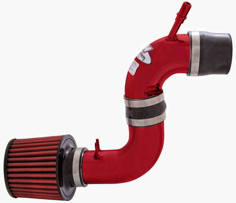
2004-2005 FORD FOCUS COLD AIR INTAKE SYSTEM PART NUMBER: 21-452 INSTALLATION INSTRUCTIONS - Read and understand these instructions BEFORE attempting to install this product. Failure to follow installation instructions and not using the provided hardware may damage the intercooler system, throttle body and engine. 1. Preparing Vehicle a. Make sure vehicle is parked on level surface. b. Set parking brake. c. If engine has run in the past two hours, let it cool down. d. Disconnect negative battery terminal. e. Raise the front of the vehicle with a jack. Refer to your owner’s manual for proper jack and jack stand placement to properly support vehicle.

Support your vehicle using properly rated jack stands before wheel removal or while working under the vehicle. NEVER WORK UNDER A VEHICLE WITHOUT USING JACK STANDS. i. Remove the driver side wheel. f. Do not discard stock components after removal of the factory system. 2. Removal of stock system d. Remove the upper air box and the bolt in the frame rail. Release the metal clamp from the Mass Air Flow (MAF) sensor housing. c. Loosen the two bolts that secure the upper air box. a. Factory air box system installed. b. Release the fitting on the inlet pipe nipple. Loosen the hose clamp at the throttle body. e. Unplug the MAF sensor. Loosen hose clamp at the bottom of the MAF housing. f. Remove the MAF housing. Confirm that the air straightener is still attached to the lower opening. g. From underneath the vehicle, remove the two screws that secure the splash shield. h. Pull the air snorkel from the splash shield and remove the splash shield. i. Remove the two screws at the upper rear section of the lower air box. j. Remove the screw at the upper front section of the lower air box. Remove the lower air box. 3. Installation of AEM® Intake System a.

When installing the intake system, do not completely tighten the hose clamps or mounting hardware until instructed to do so. b. Place the rubber reducer and hose clamps onto the throttle body. c. Secure the upper inlet pipe to MAF housing with the supplied bolts. d. Place the silicone reducer onto the MAF housing. e. Install the upper pipe onto the throttle body. Attach the breather hose to nipple on the intake pipe.

Download : 2004-2005 FORD FOCUS COLD AIR INTAKE SYSTEM PART NUMBER: 21-452 INSTALLATION INSTRUCTIONS

Selasa, 28 April 2015

2000 Ford Pickup F250 Super Duty EXHAUST BACKPRESSURE (EBP) SENSOR

carmarzus.blogspot.com
2000 Ford Pickup F250 Super Duty EXHAUST BACKPRESSURE (EBP) SENSOR -
SELF-DIAGNOSTICS – EEC-V (DIESEL) -2000 Ford Pickup F250 Super Duty EXHAUST BACKPRESSURE (EBP) SENSOR. Perform this test when directed by QUICK TEST. This test is intended to diagnose: Exhaust Backpressure (EBP) Sensor • Wiring Harness Circuits (SIG RTN, VREF & EBP Signal) • Powertrain Control Module (PCM) • 1) DTC P0470 This DTC indicates PCM detected EBP sensor malfunction during KOEO ON-DEMAND SELF-TEST. Possible causes for this DTC are: Faulty EBP Sensor • Open Or Shorted Circuit • Faulty PCM • Ensure scan tool is connected to Data Link Connector (DLC). Using scan tool, select EBP PID from PID/DATA monitor menu. If EBP reading is less than 18.5 psi, clear DTCs. Repeat KOEO ON-DEMAND SELF-TEST . If DTC is still present, replace PCM. If EBP reading is 18.5 psi or more, go to next step. 2) Check Signal Ground Circuit Turn ignition off.

Disconnect EBP sensor connector. Sensor is located on top front of engine. Inspect for damaged pins, corrosion and loose wires. Repair as necessary. Measure resistance between ground and Gray/Red wire at EBP sensor wiring harness connector. See Fig. 11 . If resistance is less than 5 ohms, replace EBP sensor. If resistance is 5 ohms or more, locate and repair open circuit in Gray/Red wire. 3) Continuous DTC P0470 This DTC indicates PCM detected a EBP sensor malfunction during normal driving conditions. Possible causes for this DTC are: Faulty EBP Sensor • Faulty Connection • Faulty PCM • Ensure scan tool is connected to Data Link Connector (DLC). Using scan tool, select EBP PID from PID/DATA monitor menu. While observing EBP PID, wiggle and bend small sections of wiring harness starting at EBP sensor connector and working toward PCM. If EBP reading fluctuates, isolate fault and repair as necessary.

If reading does not fluctuate, go to next step. 4) Check Connector Disconnect EBP sensor connector. Sensor is located on top front of engine. Disconnect PCM 104-pin connector. Inspect connectors for damaged pins, corrosion and loose wires. Repair as necessary. Clear DTCs and repeat QUICK TEST . If both connectors are okay, no problem is indicted at this time. 5) DTC P0471 This DTC indicates PCM detected an EBP sensor malfunction during normal driving conditions and with EBP sensor enabled. Possible causes for this DTC are: Faulty EBP Sensor. • Plugged Or Restricted Sensor Supply Tube • Damaged Exhaust Pressure Regulator (EPR) Linkage Or Butterfly Damage • Faulty PCM • Perform KOER ON-DEMAND SELF-TEST . If any DTCs are present, repair fault(s) before continuing with this test. Using scan tool, select EBP PID from PID/DATA monitor menu. Road test vehicle performing hard accelerations while monitoring EBP PID. If EBP reading increases to more than 25 psi with EBP sensor on, no problem is indicated at this time. If EBP reading does not increase to more than 25 psi, go to next step.
Download :  2000 Ford Pickup F250 Super Duty EXHAUST BACKPRESSURE (EBP) SENSOR

1999-2003 FORD SUPER DUTY F SERIES HIGH PRESSURE OIL PUMP LEAK

http://ww2.justanswer.com/uploads/jmcdo28/2009-10-27_012423_tsb04-04-04.pdf
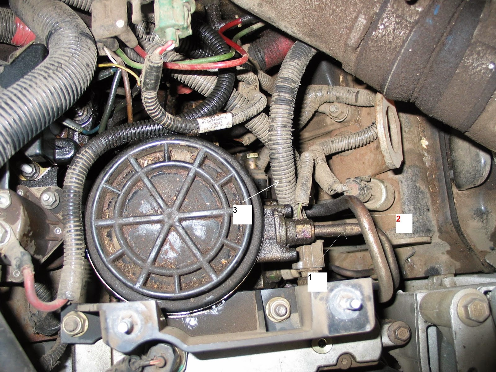
1999-2003 FORD SUPER DUTY F SERIES HIGH PRESSURE OIL PUMP LEAK - FORD: 1998-2003 E SERIES 1999-2003 SUPER DUTY F SERIES 2000-2003 EXCURSION, F-650, F-750 This article supersedes TSB 03-21-50 to update the WARNING service procedure and illustration. DO NOT REMOVE OR ATTEMPT TO REPAIR A LEAK AT THE PLUG PICTURED IN LOWER LEFT ISSUE CORNER OF FIGURE 1, OR DAMAGE TO THE Some 1998-2003 E-Series, 1999-2003 Super Duty, PUMP WILL RESULT. 2000-2003 Excursion, and 2000-2003 F650/750 1998-2003 E-SERIES HIGH PRESSURE OIL vehicles equipped with a 7.3L Diesel engine may PUMP ACCESS PROCEDURE (DISASSEMBLY) exhibit an oil leak at the high pressure oil pump outlet fittings and/or end plug (see Figure 1).

The 1. Remove the Intake Air Resonator. For leak may appear to be a rear main crankshaft seal, additional information, refer to Section 303-12 in oil pan gasket, or other engine oil leak due to the the appropriate Workshop Manual. drain hole machined in the crankcase valley which allows any oil in the valley to run down the back of 2. Remove the exhaust back pressure sensor. the engine. a.

Disconnect the exhaust back pressure ACTION sensor electrical connector. High pressure oil pump leaks at the outlet fittings b. Remove the exhaust back pressure sensor. and/or end plug can be serviced without removing the pump assembly. Replace the O-rings on the 3. Remove the high pressure oil pump reservoir. fittings and the end plug using Kit 2C3Z-9G804-AA. For additional information, refer to Section All three (3) O-rings should be replaced. Apply 303-04 in the appropriate Workshop Manual. liquid thread sealer (included in the kit) prior to WARNING reinstallation.

Refer to the following Service Procedure for details. 4. Open the fuel/water separator drain valve to FOLLOW THE PROPER HIGH PRESSURE OIL release fuel pressure. Completely drain the fuel PUMP ACCESS PROCEDURE IN THIS filter/water separator assembly. DOCUMENT FOR ACCESS TO THE HIGH 5. Disconnect the fuel supply and fuel return lines PRESSURE OIL PUMP. from the fuel filter/water separator. NOTE 6. Disconnect the two (2) cylinder head fuel FOR SUPER DUTY AND EXCURSION, PROCEED supply lines from the fuel filter/water separator. TO O-RING SEAL REPLACEMENT PROCEDURE.

Download : 1999-2003 FORD SUPER DUTY F SERIES HIGH PRESSURE OIL PUMP LEAK

Kamis, 23 April 2015

2002 Ford Taurus WATER IN THE BLOWER CASE

http://carmarzus.blogspot.com/
2002 Ford Taurus WATER IN THE BLOWER  - FORD: 2001-2004 Taurus MERCURY: 2001-2004 Sable This article supersedes TSB 03-15-06 to update the vehicle model years and build date information. ISSUE Some vehicles built between 5/1/2001 and 12/15/2003 may exhibit water in the blower case or on the passenger side floor, an inoperative climate control blower motor , a motor that operates on high speed only, and/or a blower motor resistor failure. ACTION Inspect and seal cowl area and install Rain-Hat Extension Seal. Inspect and replace blower motor and/or blower motor resistor if there is evidence of water/corrosion. Refer to the following Service Procedure for details. SERVICE PROCEDURE 1. Access blower motor and resistor per the Workshop Manual Sections 412-02 and 412-04. Inspect for evidence of water/corrosion. If water/corrosion are found or parts have failed, replace per Workshop Manual (blower motor 1F1Z- 19805-AA and resistor F6DZ-19A706-AA). 2. Visually inspect the Cowl Vent Screen located under the RH windshield wiper to verify if the screen is fully seated. Inspect the rubber seal on the vent screen which should be fully seated against the windshield. If the cowl vent screen is not fully seated and appears warped, it must be replaced (4F1Z-54018A16- BAA).

 3. Remove the cowl vent screen per the Workshop Manual Section 412-01 Pollen Filter Removal and inspect the cabin filter to confirm it is fully seated. Re-seat the filter as necessary. Inspect rain-hat base to make sure it is secure and sealed to the body. Reposition and reseal as necessary using Clear Silicone Rubber TA-32. 4. Remove the foam sealant expulsion at lower front outboard corner base of the rain-hat (Figure 1). 5. Locate the tape as shown (Figure 2). Remove the tape and apply Clear Silicone Rubber TA-32 to the small hole as shown (Figure 2). 6. Install the Rain-Hat Extension Seal or Shed Lip Seal 4F1Z-54022A54-AA to the outboard edge of the rain-hat (see Figure 2 for installation).

The 10 mm by 10 mm (0.5″ by 0.5″) cut area, located 25 mm (1″) from the end of the seal, will face down and locate at the 90 degree bend of the rain-hat on the fender side (Figure 3). 7. Prior to installation of the cowl vent screen, verify that the cabin filter cover is properly snapped in place and the clip is located on the inboard side, (toward the center of the bulkhead), the cover will feel loose if not properly snapped in place. Reinstall the cowl vent screen per Section 412-01 of the Workshop Manual.

Rabu, 22 April 2015

Ford Focus PRO-FIT Linear Fuel Doors

Ford Focus PRO-FIT Linear Fuel Doors - Tools you will need: ? Ratchet set ? Flathead screwdriver ? Drill and drill bits (for electric locking fuel door only) ? Small file ? Degreaser ? Clear Rags Parts list (items not to scale):1) Fuel door with pull cable attached (pull cable is on electric locking fuel door only) 2) Wiring harnesses (long and short) with actuator (electric locking fuel door only) 3) L-bracket (x 4) 4) Washer (x 4) 5) Nylock nut (x 4) 6) Long hex bolt (x 4) 7) Short hex bolt (x 6) 8) Fuse taps (3 sizes – electric locking fuel door only) 9) Fuse (electric locking fuel door only) 10) Switch (electric locking fuel door only) 11) Sticky pads (electric locking fuel door only) 12) Tie wraps (electric locking fuel door only) 13) Gas cap 14) Wrenches 15) Black strip caulk (not pictured) PRO-FIT Linear Fuel Doors Ford Focus – Installation Instructions Prep WARNING: Do not perform this install near a flame source due to the risk of fire or explosion from gas fumes.

 Use a jack to lift rear of vehicle. Remove the passenger side rear tire. Remove the wheel well cover to expose the fuel filler neck behind the quarterpanel. Note: For manual locking or manual non-locking fuel doors, do steps 1-4 only. For electric locking fuel doors, do all steps. Step 1 – Remove stock fuel door Remove the stock fuel door and plastic surround. The stock fuel door and plastic surround are a single unit. To remove, reach up behind the quarterpanel and release the tab at the top of the plastic surround. You may need to use a screwdriver to release the tab. Pull the stock fuel door and plastic surround straight out from the front. Step 2 – Bend tabs Bend the four tabs around the quarterpanel hole slightly inward using the back of a screwdriver handle or other blunt object.

This is to allow clearance for the back of the fuel door ring (Fig. 1, black arrows). Step 3 – Shift fuel filler neck In order for the fuel door linear mechanism to function correctly, it must clear the metal collar surrounding the fuel filler neck (Fig. 5, arrow shows contact between the linear mechanism and collar). The fuel filler neck must be shifted to the left (towards the rear of the car) to make room (Fig. 1, white arrow). Loosen the 2 bolts holding the fuel filler neck to the body (Fig. 2 and 3, arrows) and shift the entire fuel filler neck towards the rear of the vehicle. Retighten.
Download :  Ford Focus PRO-FIT Linear Fuel Doors Installation Instructions

Kamis, 09 April 2015

PMT 2008 Ford 6.4L PowersTroke Version 1.0.1.2

PMT 2008 Ford 6.4L PowersTroke Version 1.0.1.2 - This is a temporary document that describes the steps needed to install the Ford 6.4L Power stroke file onto the PMT. This document will be consolidated into the complete PMT installation manual as soon as development is complete for the GM 6.6L duramax LMM and 6.7L d odge Cummins applications are also complete. The installation topics covered in this document include: • PMT Fixed Dash Mount • Parts Installation • Uploading the 6.4L files from the Update Agent to the SD card • Uploading the 6.4L Files from the SD card to the PMT • Verify 6.4L File Upload • Install Download • Download Features • Transmission Tuning • Monitoring Features • Pyrometer Location and Overview • Defueling Features. The Fixed dash Mount for the 6.4L Ford Power stroke is an option that is sold separately (s ee product data sheet for pricing info). The Fixed dash Mount places the PMT into a location that is easily accessible to the driver and out of the view of the road. For instructions on attaching the PMT cradle to the Fixed dash mount refer to the PMT instruction set. refer to the PMT installation Manual to identify the parts described below. The installation overview provides a quick reference installation guide for the LMM. see the install overview below. There are three general steps that need to take place to install the PMT on the 6.4L Power stroke to complete the installation of the parts: 1. The first step in installing the PMT and all of the parts is determining the mounting position for the PMT. There are two mounting positions offered for the PMT: add on dash Mount and Universal dash mount. see the back PMT mounting section in this document for reference to the add on dash Mount. refer to the PMT instruction manual for universal dash Mount installation instructions.

2. The second step includes running the Cradle Cable from the PMT mounting position down to the oBd ll block, and plugging it into the oBd ll block. see the oBd ll diagram below to see the location of the oBd ll port and how the Cradle Cable plugs into the oBd ll block. For in- depth instructions refer to the PMT installation manual. 3. run the Power Wire down near the oBd ll port like the Cradle Cable. Locate the accessory wires tucked under the dash behind the oBd ll port (see oBd ll diagram). Use the snap connected to tap into the lavander accessory wire. The label around the accessory wires will identify the correct wire with the label: LV inG (10a).

Popular Posts

Twitter Facebook More

 
Design by Free WordPress Themes | Bloggerized by Lasantha - Premium Blogger Themes | Affiliate Network Reviews