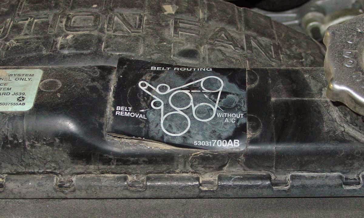
1997 Jeep Cherokee Serpentine Belt INSPECTION ADJUSTMENT REMOVAL & INSTALLATION - 1997 Jeep Cherokee 2WD 4.0L MFI 6cyl | Repair Guides. eep Wagoneer/Command o/Cherokee 1984-1998 Serpentine Belt INSPECTION ADJUSTMENT REMOVAL & INSTALLATION INSPECTION When inspecting serpentine drive belts, small cracks that run across the ribbed surface of the belt from rib to rib are considered normal.
If the the cracks are running along the rib (rather across), this is not normal and the belt(s) must be replaced. ADJUSTMENT It is not necessary to adjust belt tension on the 5.2L or 5.9L engines and on the 2.5L and 4.0L engines (without power steering). These engines are equipped with an automatic tensioner. The tensioner maintains correct tension at all times. 2.5L and 4.0L Engines With Power Steering See Figures 1, 2, 3 and 4 If the vehicle is not equipped with power steering, it will be equipped with an idler pulley. If equipped with an idler pulley, refer to and follow the 5.2L/5.9L belt removal and installation procedure. Loosen the pump upper pivot bolt, lower locknut and pump adjusting bolt using a ratchet and 13mm socket or a 13mm box wrench.
1. Use a belt tension gauge placed in the middle of the belt being tested. Proper tension for a new belt is 180-200 lbs. (800-900 N) and 140-160 lbs. (623-712 N) for a used belt. 2. Tighten the pump adjusting bolt to achieve proper tension and recheck the belt tension. 3. Removal & Installation 2.5L and 4.0L Engines With Power Steering 1. Loosen the pump upper pivot bolt, lower locknut and the pump adjusting bolt using a ratchet and 13mm socket or a 13mm box wrench. 2. Remove the belt. 3. To install: Install the belt. 4. Tighten the pump adjusting bolt to achieve proper tension. 5. Install the pump rear mounting bolts, pivot bolt and locknut. Tighten the bolts to 20. ft. lbs. (27 Nm). 6. Check the belt for proper tension. If tension is incorrect, refer to the adjustment procedure in this section. 7.
Download : 1997 Jeep Cherokee Serpentine Belt INSPECTION ADJUSTMENT REMOVAL & INSTALLATION


 17.58
17.58
 Unknown


%2BSENSOR.jpg)


