Rabu, 29 April 2015

AUDI TT Sport Sway Bar Kit 22806

http://carmarzus.blogspot.com
AUDI TT Sport Sway Bar Kit 22806 - Installation of Hotchkis Front Sway Bar 1F Raising Vehicle Raise front of the vehicle by using a 4 post lift or drive-on ramps. Securely block the rear wheels of the vehicle. Do not remove the front wheels during installation for safety. 2F Observe Orientation Of the Bar Remove the lower splash shield, and observe the location and orientation of the front swaybar. 3F Remove End Links Locate and remove the lower end link nuts from both sides, and push links aside. 4F Remove Engine Mount Locate and remove lower engine mount that attaches to subframe.

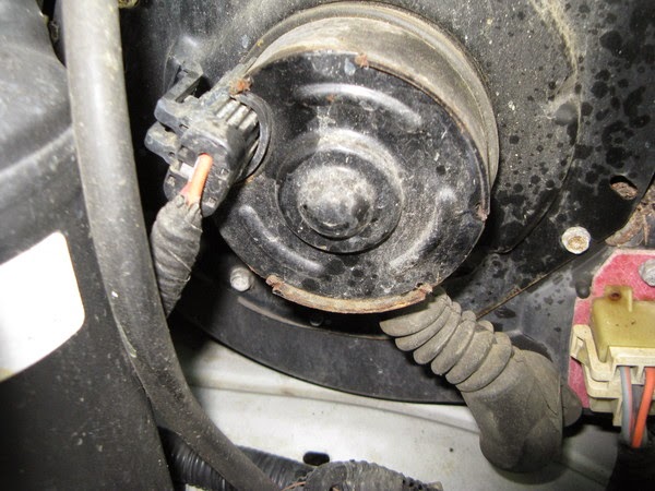
The engine may want to shift forward which is ok. 5F Remove Exhaust Hanger Use a pry bar to remove the exhaust hanger located behind subframe. 6F Ride Height Sensor Locate the ride height sensor located on the drivers side lower control arm, and remove the nut from the stud that attaches the sensor to the arm. (Be careful, this part can break easily). 7F Sub Frame Support the sub frame with a jack, and locate and remove the 4 sub frame bolts that attach it to the chassis. Lower the jack until the sub frame is at full droop, and slightly pry down until you can access the sway bar bolts. (Don’t worry, it will not fall being that it is still attached to the struts.) 8F Remove the Sway Bar Now remove the sway bar brackets that attach it to the sub frame.

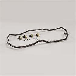
The drivers side bracket has a clamp for the power steering lines that must be removed in order to completely remove the bracket. (It does not need to be re-installed.) Now you can remove the sway bar. 9F Installation Place the new swaybar next to the factory bar so that you will be familier with the oriention that the bar is installed. Apply a good amount of the silicon grease that is supplied with the bushings, and install the bushings on the bar. After the swaybar is mounted the subframe, there is a line clamp bolted to the front of the rack & pinion on the passenger side that needs to be rotated 180 degrees in order to allow free articulation of the sway bar. Now the rest of the installation can be done in reverse order as the removal. You may need a jack to help place the subframe in the proper location.

Download : AUDI TT Sport Sway Bar Kit 22806

2007 Ford Focus Accessories List Guide

2007 Ford Focus Accessories List Guide - “Mobile-ease™” Hands Free System Connector Wiring Harness Required for Installation of “Mobile-ease™” Hands Free System 3W4Z-14A411-AA 2005-2007 Hands Free System Requires Connector Harness 14A411 for Installation3W4Z-19G399-AA2005-2007 “Street Appearance Package” ZX3/ZX5 Includes Front & Rear Bumper Fascia & Chromed Exhaust Tip, Primed 6S4Z-6120049-AA 2006-2007 ZX4 Includes Front & Rear Bumper Fascia & Chromed Exhaust Tip, Primed 6S4Z-5420049-BA 2006-2007 Bug Shield Styled Smoke-Color (Single-Pack) 5S4Z-16C900-A 2005-2007 Cargo Area Protector 3-Door/5-Door Black 1M5Z-6111600-AA 2001-2007 Sedan Black 1M5Z-5411600-DA 2001-2007 Wagon Black 1M5Z-7411600-CA 2001-2007 Cargo Logic System Without Logo Sedan, Heathered Black Ink (00) 3M5Z-5411600-AA 2003-2007 3-Door Hatchback, Heathered Black Ink (00) 3M5Z-6111600-AA 2003-2007 Wagon.

Heathered Pebble (65) 3M5Z-7411600-AA 2003-2007 Wagon, Heathered Flint (64) 3M5Z-7411600-BA 2003-2007 Wagon, Heathered Black Ink (00) 3M5Z-7411600-CA 2003-2007 Cargo Net, Retention 4-Door/Wagon Envelope Style YS4Z-54550A66-AA 2000-2007 Cargo Organizer 3-Door/5-Door/Sedan Black, For Use Without Subwoofer 5M5Z-54115A00-AAA 2005-2007 Cargo Organizer, Interior Wagon Black, With Ford Logo F8CZ-54115A00-BAA 2000-2007 Cargo Security Shade For Wagon, Med. Light Flint 5S4Z-7445440-BAA 2005-2007 Med. Light Pebble 5S4Z-7445440-BAB 2005-2007 Cover, Front End Full, Black 5S4Z-19A413-AA 2005-2007 Deflectors, Side Window 3-Door 2-Piece Set, Smoke-Color YS4Z-18246-AA 2001-2007 2-Piece Set, Smoke-Color (Bulk Pack of 10) YS4Z-18246-BA 2001-2007 2-Piece Set, Smoke-Color (Bulk Pack of 25) YS4Z-18246-CA 2001-2007 2-Piece Set, Smoke-Color (Bulk Pack of 50) YS4Z-18246-DA 2001-2007 Sedan/5-Door 4-Piece Set, Smoke-Color YS4Z-18246-EA 2001-2007 4-Piece Set, Smoke-Color (Bulk Pack of 10) YS4Z-18246-FA 2001-2007 4-Piece Set, Smoke-Color (Bulk Pack of 25) YS4Z-18246-GA 2001-2007 4-Piece Set, Smoke-Color (Bulk Pack of 50) YS4Z-18246-HA 2001-2007 Wagon 4-Piece Set, Smoke-Color YS4Z-18246-JA 2001-2007 4-Piece Set.

 Smoke-Color (Bulk Pack of 10) YS4Z-18246-KA 2001-2007 4-Piece Set, Smoke-Color (Bulk Pack of 25) YS4Z-18246-LA 2001-2007 4-Piece Set, Smoke-Color (Bulk Pack of 50) YS4Z-18246-MA 2001-2007 Floor Mats, All Weather Molded Vinyl Front & Rear, 4-Piece Set, With Focus Logo Ebony 6S4Z-5413300-A 2001-2007 Med. Dk. Flint 6S4Z-5413300-B 2001-2007 Med. Dk. Pebble 6S4Z-5413300-C 2001-2007 Floor Mats, Carpeted Front & Rear, 4-Piece Set, With Vehicle Logo Ebony 4M5Z-5413300-AA 2005-2007 Med. Dk. Flint 4M5Z-5413300-AC 2005-2007 Med. Dk. Pebble 4M5Z-5413300-AD 2005-2007 Lights, Fog Original Equipment 5S4Z-15200-AA 2005-2007 Lock Kit, Wheel Anti-Theft Chrome Plated For Exposed Lugs, Includes (4) Lock Lugs and (1) Key

Ford Explorer Sport Trac Advanced Folding X5 Supra Cover INSTALLATION INSTRUCTIONS

Ford Explorer Sport Trac Advanced Folding X5 Supra Cover INSTALLATION INSTRUCTIONS - Advanced Folding X5 Supra Cover 2001-2006 Ford Explorer Sport Trac 2007-2010 Ford Explorer Sport Trac (Part Number’s 28570 & 28572). Suggested Tools Installation Kit â Scissors â 5/16″ Socket or Wrench â 3/8″ Wrench â Ratchet â Hammer â Chisel or knife â 1/8″ Punch or Nail â #1 Phillips Screwdriver â 4 Latch Catches for 28570 â 2 3rdLeg Hinge Brackets for 28570 â 12 Washers â 12 Latch Catch Screws â 2 D-Seals â 2 Nuts and 2 Bolts â Latch Catch Screws.

Removing Plastic Plugs 1. Cut off 8 plastic plugs (2 in each corner) with a chisel or knife and push the remaining pieces through the hole using a hammer and nail or punch. Make sure holes are clear. (Fig. 1). 2. Pry 4 plugs out (with a standard screwdriver) of the center of the sides of the truck box (2 each side). (Fig. 2). rail D seal at end of Tailgate Box Seal The torque screws located in the middle of the sides need to be removed according to the instructions. DO NOT REMOVE BOTH SCREWS AT THE SAME TIME. The bracket behind the side wall will fail. Attaching Latch Catch and Keyhole Brackets 3. Place lock washers on screws (12x). (Fig. 3). 4. Place (12) screws with lock washers on, (4) Latch catch brackets (#ST101), and (2) Keyhole brackets (#ST102) into the bed of the truck. (Fig. 4). Mounting Keyhole Bracket 5. Remove lower screw (only the lower screw) using a 30# Torque bit with ratchet. 5. Remove 1 side screw (only the 1 side screw).

6. Place one screw through the lower slot in the keyhole bracket and hand thread into hole where you just removed the torque screw. Then tighten with Phillips screwdriver. 7. After tightening the lower screw, remove upper screw. Then hand thread another screw through the upper slot of the keyhole bracket and into the upper hole where you just removed the torque screw.

Download : Ford Explorer Sport Trac Advanced Folding X5 Supra Cover INSTALLATION INSTRUCTIONS

2004-2005 FORD FOCUS COLD AIR INTAKE SYSTEM PART NUMBER: 21-452 INSTALLATION INSTRUCTIONS

http://www.aemintakes.com/instructions/AEM-21-452_inst.pdf
2004-2005 FORD FOCUS COLD AIR INTAKE SYSTEM PART NUMBER: 21-452 INSTALLATION INSTRUCTIONS - Read and understand these instructions BEFORE attempting to install this product. Failure to follow installation instructions and not using the provided hardware may damage the intercooler system, throttle body and engine. 1. Preparing Vehicle a. Make sure vehicle is parked on level surface. b. Set parking brake. c. If engine has run in the past two hours, let it cool down. d. Disconnect negative battery terminal. e. Raise the front of the vehicle with a jack. Refer to your owner’s manual for proper jack and jack stand placement to properly support vehicle.

Support your vehicle using properly rated jack stands before wheel removal or while working under the vehicle. NEVER WORK UNDER A VEHICLE WITHOUT USING JACK STANDS. i. Remove the driver side wheel. f. Do not discard stock components after removal of the factory system. 2. Removal of stock system d. Remove the upper air box and the bolt in the frame rail. Release the metal clamp from the Mass Air Flow (MAF) sensor housing. c. Loosen the two bolts that secure the upper air box. a. Factory air box system installed. b. Release the fitting on the inlet pipe nipple. Loosen the hose clamp at the throttle body. e. Unplug the MAF sensor. Loosen hose clamp at the bottom of the MAF housing. f. Remove the MAF housing. Confirm that the air straightener is still attached to the lower opening. g. From underneath the vehicle, remove the two screws that secure the splash shield. h. Pull the air snorkel from the splash shield and remove the splash shield. i. Remove the two screws at the upper rear section of the lower air box. j. Remove the screw at the upper front section of the lower air box. Remove the lower air box. 3. Installation of AEM® Intake System a.

When installing the intake system, do not completely tighten the hose clamps or mounting hardware until instructed to do so. b. Place the rubber reducer and hose clamps onto the throttle body. c. Secure the upper inlet pipe to MAF housing with the supplied bolts. d. Place the silicone reducer onto the MAF housing. e. Install the upper pipe onto the throttle body. Attach the breather hose to nipple on the intake pipe.

Download : 2004-2005 FORD FOCUS COLD AIR INTAKE SYSTEM PART NUMBER: 21-452 INSTALLATION INSTRUCTIONS

1997 Jeep Cherokee Serpentine Belt INSPECTION ADJUSTMENT REMOVAL & INSTALLATION

http://ww2.justanswer.com/uploads/JHoop/2010-08-15_191723_1.pdf
1997 Jeep Cherokee Serpentine Belt INSPECTION ADJUSTMENT REMOVAL & INSTALLATION - 1997 Jeep Cherokee 2WD 4.0L MFI 6cyl | Repair Guides. eep Wagoneer/Command o/Cherokee 1984-1998 Serpentine Belt INSPECTION ADJUSTMENT REMOVAL & INSTALLATION INSPECTION When inspecting serpentine drive belts, small cracks that run across the ribbed surface of the belt from rib to rib are considered normal.

If the the cracks are running along the rib (rather across), this is not normal and the belt(s) must be replaced. ADJUSTMENT It is not necessary to adjust belt tension on the 5.2L or 5.9L engines and on the 2.5L and 4.0L engines (without power steering). These engines are equipped with an automatic tensioner. The tensioner maintains correct tension at all times. 2.5L and 4.0L Engines With Power Steering See Figures 1, 2, 3 and 4 If the vehicle is not equipped with power steering, it will be equipped with an idler pulley. If equipped with an idler pulley, refer to and follow the 5.2L/5.9L belt removal and installation procedure. Loosen the pump upper pivot bolt, lower locknut and pump adjusting bolt using a ratchet and 13mm socket or a 13mm box wrench.

1. Use a belt tension gauge placed in the middle of the belt being tested. Proper tension for a new belt is 180-200 lbs. (800-900 N) and 140-160 lbs. (623-712 N) for a used belt. 2. Tighten the pump adjusting bolt to achieve proper tension and recheck the belt tension. 3. Removal & Installation 2.5L and 4.0L Engines With Power Steering 1. Loosen the pump upper pivot bolt, lower locknut and the pump adjusting bolt using a ratchet and 13mm socket or a 13mm box wrench. 2. Remove the belt. 3. To install: Install the belt. 4. Tighten the pump adjusting bolt to achieve proper tension. 5. Install the pump rear mounting bolts, pivot bolt and locknut. Tighten the bolts to 20. ft. lbs. (27 Nm). 6. Check the belt for proper tension. If tension is incorrect, refer to the adjustment procedure in this section. 7.

Download : 1997 Jeep Cherokee Serpentine Belt INSPECTION ADJUSTMENT REMOVAL & INSTALLATION

Selasa, 28 April 2015

2000 Ford Pickup F250 Super Duty EXHAUST BACKPRESSURE (EBP) SENSOR

carmarzus.blogspot.com
2000 Ford Pickup F250 Super Duty EXHAUST BACKPRESSURE (EBP) SENSOR -
SELF-DIAGNOSTICS – EEC-V (DIESEL) -2000 Ford Pickup F250 Super Duty EXHAUST BACKPRESSURE (EBP) SENSOR. Perform this test when directed by QUICK TEST. This test is intended to diagnose: Exhaust Backpressure (EBP) Sensor • Wiring Harness Circuits (SIG RTN, VREF & EBP Signal) • Powertrain Control Module (PCM) • 1) DTC P0470 This DTC indicates PCM detected EBP sensor malfunction during KOEO ON-DEMAND SELF-TEST. Possible causes for this DTC are: Faulty EBP Sensor • Open Or Shorted Circuit • Faulty PCM • Ensure scan tool is connected to Data Link Connector (DLC). Using scan tool, select EBP PID from PID/DATA monitor menu. If EBP reading is less than 18.5 psi, clear DTCs. Repeat KOEO ON-DEMAND SELF-TEST . If DTC is still present, replace PCM. If EBP reading is 18.5 psi or more, go to next step. 2) Check Signal Ground Circuit Turn ignition off.

Disconnect EBP sensor connector. Sensor is located on top front of engine. Inspect for damaged pins, corrosion and loose wires. Repair as necessary. Measure resistance between ground and Gray/Red wire at EBP sensor wiring harness connector. See Fig. 11 . If resistance is less than 5 ohms, replace EBP sensor. If resistance is 5 ohms or more, locate and repair open circuit in Gray/Red wire. 3) Continuous DTC P0470 This DTC indicates PCM detected a EBP sensor malfunction during normal driving conditions. Possible causes for this DTC are: Faulty EBP Sensor • Faulty Connection • Faulty PCM • Ensure scan tool is connected to Data Link Connector (DLC). Using scan tool, select EBP PID from PID/DATA monitor menu. While observing EBP PID, wiggle and bend small sections of wiring harness starting at EBP sensor connector and working toward PCM. If EBP reading fluctuates, isolate fault and repair as necessary.

If reading does not fluctuate, go to next step. 4) Check Connector Disconnect EBP sensor connector. Sensor is located on top front of engine. Disconnect PCM 104-pin connector. Inspect connectors for damaged pins, corrosion and loose wires. Repair as necessary. Clear DTCs and repeat QUICK TEST . If both connectors are okay, no problem is indicted at this time. 5) DTC P0471 This DTC indicates PCM detected an EBP sensor malfunction during normal driving conditions and with EBP sensor enabled. Possible causes for this DTC are: Faulty EBP Sensor. • Plugged Or Restricted Sensor Supply Tube • Damaged Exhaust Pressure Regulator (EPR) Linkage Or Butterfly Damage • Faulty PCM • Perform KOER ON-DEMAND SELF-TEST . If any DTCs are present, repair fault(s) before continuing with this test. Using scan tool, select EBP PID from PID/DATA monitor menu. Road test vehicle performing hard accelerations while monitoring EBP PID. If EBP reading increases to more than 25 psi with EBP sensor on, no problem is indicated at this time. If EBP reading does not increase to more than 25 psi, go to next step.
Download :  2000 Ford Pickup F250 Super Duty EXHAUST BACKPRESSURE (EBP) SENSOR

1999-2003 FORD SUPER DUTY F SERIES HIGH PRESSURE OIL PUMP LEAK

http://ww2.justanswer.com/uploads/jmcdo28/2009-10-27_012423_tsb04-04-04.pdf
1999-2003 FORD SUPER DUTY F SERIES HIGH PRESSURE OIL PUMP LEAK - FORD: 1998-2003 E SERIES 1999-2003 SUPER DUTY F SERIES 2000-2003 EXCURSION, F-650, F-750 This article supersedes TSB 03-21-50 to update the WARNING service procedure and illustration. DO NOT REMOVE OR ATTEMPT TO REPAIR A LEAK AT THE PLUG PICTURED IN LOWER LEFT ISSUE CORNER OF FIGURE 1, OR DAMAGE TO THE Some 1998-2003 E-Series, 1999-2003 Super Duty, PUMP WILL RESULT. 2000-2003 Excursion, and 2000-2003 F650/750 1998-2003 E-SERIES HIGH PRESSURE OIL vehicles equipped with a 7.3L Diesel engine may PUMP ACCESS PROCEDURE (DISASSEMBLY) exhibit an oil leak at the high pressure oil pump outlet fittings and/or end plug (see Figure 1).

The 1. Remove the Intake Air Resonator. For leak may appear to be a rear main crankshaft seal, additional information, refer to Section 303-12 in oil pan gasket, or other engine oil leak due to the the appropriate Workshop Manual. drain hole machined in the crankcase valley which allows any oil in the valley to run down the back of 2. Remove the exhaust back pressure sensor. the engine. a.

Disconnect the exhaust back pressure ACTION sensor electrical connector. High pressure oil pump leaks at the outlet fittings b. Remove the exhaust back pressure sensor. and/or end plug can be serviced without removing the pump assembly. Replace the O-rings on the 3. Remove the high pressure oil pump reservoir. fittings and the end plug using Kit 2C3Z-9G804-AA. For additional information, refer to Section All three (3) O-rings should be replaced. Apply 303-04 in the appropriate Workshop Manual. liquid thread sealer (included in the kit) prior to WARNING reinstallation.

Refer to the following Service Procedure for details. 4. Open the fuel/water separator drain valve to FOLLOW THE PROPER HIGH PRESSURE OIL release fuel pressure. Completely drain the fuel PUMP ACCESS PROCEDURE IN THIS filter/water separator assembly. DOCUMENT FOR ACCESS TO THE HIGH 5. Disconnect the fuel supply and fuel return lines PRESSURE OIL PUMP. from the fuel filter/water separator. NOTE 6. Disconnect the two (2) cylinder head fuel FOR SUPER DUTY AND EXCURSION, PROCEED supply lines from the fuel filter/water separator. TO O-RING SEAL REPLACEMENT PROCEDURE.

Download : 1999-2003 FORD SUPER DUTY F SERIES HIGH PRESSURE OIL PUMP LEAK

Test Guidelines for Use of Essential Tool J 41413-200 Evaporative System Tester

Test Guidelines for Use of Essential Tool J 41413-200 Evaporative System Tester - Models: 2002 and Prior Passenger Cars and Light Duty Trucks with Non-Enhanced and Enhanced EVAP Systems. Non-Enhanced EVAP System Diagnostic Procedure 1. Pinch off or plug the EVAP vapor line to seal the EVAP system. 2. Connect the EEST red battery clip to the positive (+) battery terminal.

Connect the black battery clip to chassis ground. 3. Install the appropriate fuel fill cap adapter to the fuel fill pipe. Refer to the Service Information for the appropriate fuel fill cap adapter part number. 4. Connect the EEST’s nitrogen/smoke supply hose and vehicle fuel fill cap to the adapter. 5. Turn the nitrogen/smoke valve on the EEST control panel to SMOKE. 6. Use the remote switch to introduce smoke into the EVAP system for 60 seconds.

 Important: Additional smoke may need to be introduced at 15-second intervals until the leak source has been located. 7. Inspect the entire EVAP system for exiting smoke using the high intensity white light (J 41413-SPT). Enhanced EVAP System Leak Detection Procedure When diagnosing DTCs P0440, P0442, P0446 and P0455, use the J 41413-200 EEST along with Subject: Test Guidelines for Use of Essential Tool J 41413-200 Evaporative System Tester Models: 2002 and Prior Passenger Cars and Light Duty Trucks with Non-Enhanced and Enhanced EVAP Systems the following procedure anytime the diagnostic calls for the J 41413 EVAP Pressure/Purge Diagnostic Station. Important: ENSURE THAT THE VEHICLE UNDERBODY TEMPERATURE IS SIMILAR TO THE AMBIENT TEMPERATURE AND ALLOW THE SURROUNDING AIR TO STABILIZE BEFORE STARTING THE DIAGNOSTIC PROCEDURE. 1. Turn ON the ignition with the engine OFF. 2. Command the EVAP vent valve closed with a scan tool.* *Prizm: In order to seal the EVAP system on the 1998-2002 Prizm, bypass the EVAP canister by connecting the fuel tank vapor hose to the canister purge line. Refer to the Service Information for additional information. 3. Connect the EEST red battery clip to the positive (+) battery terminal.

Connect the black battery clip to chassis ground. 4. Install the appropriate fuel fill cap adapter to the fuel fill pipe. Refer to the Service Information for the appropriate fuel fill cap adapter part number. 5. Connect the EEST’s nitrogen/smoke supply hose and vehicle fuel fill cap to the adapter. 6. Turn the nitrogen/smoke valve on the EEST control panel to SMOKE. 7. Use the remote switch to introduce smoke into the EVAP system. 8. Use the J 41413-VLV EVAP Port Vent Fitting tool to open the EVAP service port (if equipped) until smoke is observed.
Download : Test Guidelines for Use of Essential Tool J 41413-200 Evaporative System Tester

2001-2002 Honda Odyssey Idle Fluctuation and/or the MIL Is On With DTC P1129

http://carmarzus.blogspot.com/
2001-2002 Honda Odyssey Idle Fluctuation and/or the MIL Is On With DTC P1129 -
2001-02 Odyssey – ALL 2003 Odyssey – From VIN 5FNRL1…3B000001 thru 5FNRL1…3B159953 2003 Odyssey – From VIN 2HKRL1…3H500001 thru 2HKRL1…3H514354 2003 Pilot – From VIN 2HKYF1…3H500001 thru 2HKYF1…3H520648 Idle Fluctuation and/or the MIL Is On With DTC P1129 and/or P0505 (Supersedes 04-007, Idle Fluctuation With DTC P1129 , dated February 6, 2004, to update the information marked by the black bars) SYMPTOM The idle fluctuates, and/or the MIL is on with DTC P1129 (high manifold absolute pressure [MAP] sensor signal) and/or P0505 (faulty IAC valve).

 PROBABLE CAUSE The idle air control (IAC) valve sticks open, the power steering pressure switch wire is broken, or both. CORRECTIVE ACTION Replace the IAC valve, repair the power steering pressure switch wire, or do both. DIAGNOSIS 1. Start the engine, and let it idle until it warms up. Does the idle fluctuate, or is there a customer complaint of an intermittent idle fluctuation? Yes – Odyssey : Go to REPAIR PROCEDURE A. Pilot : Go to REPAIR PROCEDURE B. No – Go to step 2. 2. Connect the HDS to the vehicle’s DLC, and check for DTCs. Is DTC P1129 or P0505 stored? Yes – Go to REPAIR PROCEDURE B. No – Continue with normal troubleshooting. REPAIR PROCEDURE A 1. Connect the HDS to the vehicle’s DLC. 2. Start the engine, and turn on the HDS. 3. When prompted, enter the VIN and the odometer reading. 4. From the System Selection Menu screen, select PGM-FI . 5. From the Mode Menu, select DATA LIST . 6. Scroll down the list to PSP SWITCH . Watch the reading in the Value column. 7. Check for a broken power steering pressure switch wire by wiggling the P/S pressure switch wire harness at the switch while you check the Value column reading. •If the reading changes between on and off when you wiggle the harness, go to step 8. •If the reading does not change between on and off when you wiggle the harness, go to REPAIR PROCEDURE B. 8. Raise the vehicle on a lift, and remove the right front wheel to access the power steering pressure switch. 9. Disconnect the connector from the switch, and release the harness clip from the body.

NOTE: You may need to disconnect the Secondary HO2S connector to free the end of the harness from the body. 10. Lower the vehicle, and pull the harness up for easier access to make the repair. 11. Remove the rubber seal from the connector, and remove the terminals from the connector noting the GRN wire and BLK wire locations. 12. Remove the tape from the corrugated tube and the wires up to the harness clip; mark the wires at the end of the corrugated tube.

Download :  2001-2002 Honda Odyssey Idle Fluctuation and/or the MIL Is On With DTC P1129

2006 Dodge Truck RAM DENSO A/C COMPRESSOR

http://carmarzus.blogspot.com/
 2006 Dodge Truck RAM DENSO A/C COMPRESSOR - 2006 Dodge Truck RAM 2500 Truck 2WD L6-5.9L DSL Turbo VIN C Vehicle Level Heating and Air Conditioning Compressor HVAC Compressor Clutch Service and Repair Service and Repair. DENSO A/C COMPRESSOR REMOVAL NOTE: * The compressor clutch assembly can be serviced with the refrigerant system fully-charged. * Typical A/C compressor shown in illustrations.

1. Disconnect and isolate the negative battery cable. 2. Remove the accessory drive belt. 3. Disconnect the engine wire harness from the compressor clutch field coil connector (1) located on the top of the A/C compressor (5). 4. Remove the bolts that secure the A/C compressor to the engine and support the A/C compressor. 5. Carefully remove the compressor clutch field coil connector and wire lead from the connector bracket (2). 6. Remove the compressor shaft bolt (3). A band-type oil filter wrench or a strap wrench may be used to hold the clutch plate (4) from rotating during bolt removal. CAUTION: Do not pry between the clutch plate and the pulley and bearing assembly to remove the clutch plate from the compressor shaft as this may damage the clutch plate. NOTE: Use care not to lose any clutch shim(s) during removal of the clutch plate, as they may be reused during the clutch plate installation process. 7. Tap the clutch plate (2) lightly with a plastic mallet to release it from the splines on the compressor shaft (1) and remove the clutch plate and shim(s) (3).

8. Using snap ring pliers (2), remove the snap ring (1) that secures the pulley and bearing assembly (3) to the front of the A/C compressor and remove the pulley and bearing assembly. 9. Using snap ring pliers (Special Tool C-4574 or equivalent) (1), remove the snap ring (4) that secures the compressor clutch field coil (2) to the front of the A/C compressor (3) and remove the field coil. INSTALLATION NOTE: Typical A/C compressor shown in illustrations. 1. Align the dowel pin on the back of the compressor clutch field coil (2) with the hole in the front of the A/C compressor (3) and position the field coil onto the compressor. Be certain that the compressor clutch field coil wire lead is properly routed so that it is not pinched between the A/C compressor and the field coil.

CAUTION: The snap ring must be fully and properly seated in the groove or it will vibrate out, resulting in a clutch failure and severe damage to the A/C compressor. NOTE: A new snap ring must be used to secure the compressor clutch field coil to the A/C compressor. The bevel side of the snap ring must face outward and both snap ring eyelets must be oriented to the right or to the left of the field coil dowel pin location on the A/C compressor.

Download :  2006 Dodge Truck RAM DENSO A/C COMPRESSOR

Jumat, 24 April 2015

2001 Hyundai Accent GS Transmission Speed Sensor

http://carmarzus.blogspot.com/
2001 Hyundai Accent GS Transmission Speed Sensor - NOTE: Both pulse generator-B inspection and TCM reprogramming procedures should be performed. PULSE GENERATOR-B INSPECTION PROCEDURE: 1. Open and secure the hood. 2. Remove the resonator. 3. Locate the pulse generator under the battery tray.

Disconnect the pulse generator connector (blue) and remove the pulse generator male connector (black) from the bracket. 4. Using an ohmmeter, check the resistance between terminal No. 3 and No. 4 in the disconnected pulse generator male connector (black color). Resistance value: 215-275W (at 20°C or 68°F) If the resistance is lower or higher than the specification, replace the pulse generator (P/N 45955-22700). If the resistance is within specification go to Step 5. 5. Clean both ends of the disconnected pulse generator connectors with aerosol electrical contact cleaner.


6. Apply contact grease (P/N 00305-F0000-39, NYOGEL 760G), into all four terminal openings of the blue female connector until each terminal opening is completely filled with grease. 7. Reconnect the pulse generator connectors and reattach the connector to the bracket. Reinstall all removed components in the reverse order of removal. TCM SPECIFICATIONS CAUTIONS BEFORE REPROGRAMMING: 1. Conduct reprogramming with the ignition key in the “ON” position. 2. Be careful not to disconnect any cables connected to the vehicle or Hi-Scan Pro during reprogramming. 3. Do not start the engine or turn the ignition key off during reprogramming.

WARNING: If reprogramming is interrupted, the manual update procedure must be used. 4. When the reprogramming is completed, turn off the ignition key for 20 seconds before starting the engine. TCM REPROGRAMMING PROCEDURE: 1. Insert the 16 MB reprogramming card into the top slot of the Hi-Scan Pro.

Download : 2001 Hyundai Accent GS Transmission Speed Sensor

2004-2006 Chevrolet Malibu Loss of Power Steering Assist

http://ww2.justanswer.com/uploads/heavychevy396/2010-02-04_232952_Loss_of_Power_Steering_Assist,_PowerSteering_Warning_Message_Displayed_in_DIC,IPC_Radio_Displays_Erratic.pdf
2004-2006 Chevrolet Malibu Loss of Power Steering Assist - Power Steering Warning Message Displayed in DIC, IPC/Radio Displays Erratic, DTC C0900, B1325 Set (Replace Ignition Coil/Module Assembly and Add Ground Strap) Models: 2004-2006 Chevrolet Malibu, Malibu Maxx with 3.5L Engine (VINs 8, N — RPOs LX9, LZ4) Condition Some customers may comment on a loss of power steering assist at high RPM (above 3500 RPM) and a power steering warning message displayed in the DIC.

They may also comment some instrument/radio displays are erratic. Upon investigation, the technician may find DTC C0900 set. If the displays were erratic, then DTC B1325 will also be set. Cause This condition may occur when the system voltage exceeds 16 volts for one second for code C0900 and the system shuts down to protect it from over-voltage operation. If the voltage exceeds 18 volts for five seconds for code B1325, then other electronic systems protect themselves and shut down. It has been found that this voltage increase is caused by an interaction between the alternator and the ignition coil/module assembly.

Correction Replace the ignition coil/module assembly and add ground strap following the procedure below. 1. Disconnect the ignition coil electrical connector. 2. Disconnect the left side spark plug wires from the ignition coil. 3. Disconnect the right side spark plug wires from the ignition coil. 4. Remove the four bolts attaching the ignition coil to its mounting bracket and remove the ignition coil. 5. Remove the ignition coil from the mounting bracket. 6. Loosen the two lower ignition coil mounting bracket nuts. 7. Remove the two upper ignition coil mounting bracket bolts and discard. 8. Install the ground strap (1), P/N 12581176, to the upper left side of the bracket as shown between the coil bracket and intake. Install the new bracket bolt, P/N 11570082, (do not tighten at this time).

Prior to installing the ground strap, remove the captured nut and washers. They are not needed (simply pound them out with a hammer on a vise). 9. Install the washer (2), P/N 02436162, to the upper right side of the bracket between the coil bracket and intake. Install the new bracket bolt, P/N 11570082, (do not tighten at this time). Tighten Tighten all the ignition coil bracket bolts and nuts to 25 N·m (15 lb ft). 10. Install the new ignition coil to the mounting bracket.

Download : 2004-2006 Chevrolet Malibu Loss of Power Steering Assist

NISSAN MAXIMA WHINING NOISE FROM TIMING CHAIN AREA

http://ww2.justanswer.com/uploads/fixurnissan/2010-04-12_184712_Timing_chain_complete_bulletin.pdf
NISSAN MAXIMA WHINING NOISE FROM TIMING CHAIN AREA - 2004-2008 Maxima (A34) 2004-2006 Altima (L31) with VQ35 engine ONLY 2004-2009 Quest (V42) IF YOU CONFIRM: There is a high frequency buzzing / whining noise coming from the secondary timing chain system. • The noise should increase in frequency with engine speed (RPM). • If the noise does not increase with engine speed, the timing chain system may not be the cause.

Refer to the appropriate section of the Electronic Service Manual (ESM) for further diagnosis. ACTION: 1. Replace both secondary timing chains and both secondary timing chain tensioner “shoes” with the ones from the PARTS INFORMATION section of this bulletin (on Page 2). 2. Change the engine oil and filter. 3. For repair procedure, refer to the SERVICE PROCEDURE section of this bulletin (starting on Page 3). SERVICE PROCEDURE Write down all radio station presets. Presets 1 2 3 4 5 6 A B C 2. Disconnect both battery cables, negative cable first. 3. Remove the secondary timing chains. Refer to the Electronic Service Manual (ESM) if needed. NOTE: It is not necessary to remove the valve covers or intake collector. • Before removing the crankshaft pulley, set it to 0° Top Dead Center (TDC). • Use Tool J-50288 to secure the flywheel / flex plate when removing the crankshaft pulley and camshaft sprockets (no picture shown).

NOTE : The camshaft sprockets’ bolts will be removed and installed while being held by all three (3) timing chains. • If the crankshaft is determined to be 360° off from 0° TDC on #1 cylinder compression stroke after removing the front timing chain case (front cover), put the crankshaft pulley back on, and then rotate the crankshaft 360° (when camshaft and crankshaft sprocket mating marks are aligned).

Download NISSAN MAXIMA WHINING NOISE FROM TIMING CHAIN AREA

1984-1995 Honda Civic/CRX Positive Crankcase Ventilation (PCV) System

http://carmarzus.blogspot.com/
1984-1995 Honda Civic/CRX Positive Crankcase Ventilation (PCV) System - SERVICE Positive Crankcase Ventilation (PCV) Valve For PCV valve removal, refer to Routine Maintenance of this information. 1. Locate the PCV valve. With the engine running at idle, use pliers to pinch the PCV hose between the valve and the intake manifold. It should be possible to hear the spring loaded valve click shut. 2. If no click is heard, remove the valve from the engine but leave it connected to the intake manifold. A hissing sound should be heard and vacuum should be felt at the valve inlet. 3. If no vacuum is felt, remove the valve from the intake manifold hose. The engine should stall or almost stall.

This will indicate a stuck valve or clogged hose. Check the breather hose for clogging or leaks and replace any defective parts. Exhaust Gas Recirculation (EGR) System FUEL INJECTED ENGINES General Information See Figure 3 The Exhaust Gas Recirculation (EGR) system is used to control emissions measured at the tailpipe. Components included are the EGR valve and controls. The EGR system uses a poppet type valve to regulate the amount of exhaust gas flowing into the intake manifold. The flow path is cast into the cylinder head and does not use any external tubing.

A control solenoid valve regulates the amount of vacuum to the EGR valve. A Constant Volume Control (CVC) valve provides a constant amount of vacuum to the control solenoid valve over a wide range of engine vacuum. When servicing or repairing any part of the emissions system, it is absolutely essential to check for any obvious mechanical faults or failures. Remember, a trouble code only indicates which sensor or circuit is affected by the problem. Simple mechanical faults such as a vacuum leak or poor electrical connection can cause a fault code. The EGR valve is not simply open or closed but is modulated by controlling the amount of engine vacuum to the valve diaphragm, up to a maximum of 8 in. Hg of vacuum.

The EGR valve has a sensor in the top of the valve that reports valve lift to the ECU (same as ECM, 1992-95). The ECU modulates the position of the control solenoid valve to control the EGR valve lift according to an internal program. Upstream of the control solenoid valve, the CVC provides a constant supply of vacuum so EGR control is precise under all manifold vacuum conditions.

Download : 1984-1995 Honda Civic/CRX Positive Crankcase Ventilation (PCV) System

Kamis, 23 April 2015

2002 Ford Taurus WATER IN THE BLOWER CASE

http://carmarzus.blogspot.com/
2002 Ford Taurus WATER IN THE BLOWER  - FORD: 2001-2004 Taurus MERCURY: 2001-2004 Sable This article supersedes TSB 03-15-06 to update the vehicle model years and build date information. ISSUE Some vehicles built between 5/1/2001 and 12/15/2003 may exhibit water in the blower case or on the passenger side floor, an inoperative climate control blower motor , a motor that operates on high speed only, and/or a blower motor resistor failure. ACTION Inspect and seal cowl area and install Rain-Hat Extension Seal. Inspect and replace blower motor and/or blower motor resistor if there is evidence of water/corrosion. Refer to the following Service Procedure for details. SERVICE PROCEDURE 1. Access blower motor and resistor per the Workshop Manual Sections 412-02 and 412-04. Inspect for evidence of water/corrosion. If water/corrosion are found or parts have failed, replace per Workshop Manual (blower motor 1F1Z- 19805-AA and resistor F6DZ-19A706-AA). 2. Visually inspect the Cowl Vent Screen located under the RH windshield wiper to verify if the screen is fully seated. Inspect the rubber seal on the vent screen which should be fully seated against the windshield. If the cowl vent screen is not fully seated and appears warped, it must be replaced (4F1Z-54018A16- BAA).

 3. Remove the cowl vent screen per the Workshop Manual Section 412-01 Pollen Filter Removal and inspect the cabin filter to confirm it is fully seated. Re-seat the filter as necessary. Inspect rain-hat base to make sure it is secure and sealed to the body. Reposition and reseal as necessary using Clear Silicone Rubber TA-32. 4. Remove the foam sealant expulsion at lower front outboard corner base of the rain-hat (Figure 1). 5. Locate the tape as shown (Figure 2). Remove the tape and apply Clear Silicone Rubber TA-32 to the small hole as shown (Figure 2). 6. Install the Rain-Hat Extension Seal or Shed Lip Seal 4F1Z-54022A54-AA to the outboard edge of the rain-hat (see Figure 2 for installation).

The 10 mm by 10 mm (0.5″ by 0.5″) cut area, located 25 mm (1″) from the end of the seal, will face down and locate at the 90 degree bend of the rain-hat on the fender side (Figure 3). 7. Prior to installation of the cowl vent screen, verify that the cabin filter cover is properly snapped in place and the clip is located on the inboard side, (toward the center of the bulkhead), the cover will feel loose if not properly snapped in place. Reinstall the cowl vent screen per Section 412-01 of the Workshop Manual.

2000 Buick Regal Oil Pan Replacement

http://carmarzus.blogspot.com/
2000 Buick Regal Oil Pan Replacement - Tools Required z J 28467-90A Engine Support Adapters z J 28467-B Universal Engine Support Fixture z J 36462-A Engine Support Adapter Leg Set 1. Disconnect the battery ground (negative) cable. Refer to Battery Negative Cable Disconnect/Connect Procedure in Engine Electrical. 2. Carefully disconnect the throttle body air inlet duct. 3. Remove the engine mount struts from the engine.

Refer to Engine Mount Strut Replacement . 4. Remove the drive belt. Refer to Drive Belt Replacement . 5. Install the J 28467-90A , the J 28467-B and the J 36462-A . Do not raise the engine. Refer to Engine Support Fixture . 6. Raise and suitably support the vehicle. Refer to Lifting and Jacking the Vehicle in General Information. 7. Disconnect the three-way catalytic converter pipe from the right exhaust manifold. Refer to Catalytic Converter Replacement in Engine Exhaust. 8. Remove the right front tire and wheel. Refer to Tire and Wheel Removal and Installation in Tires and Wheels. 9. Remove the right engine splash shield. Refer to Splash Shield Replacement – Engine in Body Front End.

10. Drain the engine oil. Refer to Engine Oil and Oil Filter Replacement. 11. Remove the oil filter. Refer to Engine Oil and Oil Filter Replacement. 12. Remove the AC compressor bracket bolts. Reposition and secure the AC compressor. 13. Disconnect the power steering oil cooler pipe brackets from the frame. 14. Remove the engine mount bracket bolts from the engine. Refer to Engine Mount and Bracket Replacement . 15. Remove the lower engine mount nuts. Refer to Engine Mount and Bracket Replacement . 16. Remove the torque converter cover. Refer to Torque Converter Cover Replacement in Automatic Transaxle – 4T65-E. 17. Disconnect the oil level sensor wiring harness connector. 18. Remove the oil level sensor. 19. Lower the vehicle. 20. Use the J 28467-B in order to raise the engine for access. 21. Raise and suitably support the vehicle. Refer to Lifting and Jacking the Vehicle in General Information. 22. Suitably support the frame. Loosen the left side frame bolts. Remove the right side frame bolts. Lower the frame for access. Refer to Frame Removal in Frame and Underbody. 23. Remove the engine mount and the engine mount bracket. 24. Remove the oil pan retaining bolts. 25. Remove the oil pan. 26. Remove the oil pump pipe and screen assembly and the oil pan gasket. 27. Clean the following parts: { The oil pan flanges { The oil pan rail { The front cover { The rear main bearing cap { The threaded holes Installation Procedure 1. Install the oil pan gasket and the oil pump pipe and screen assembly.

Tighten Tighten the oil pump pipe and screen bolts to 15 N·m (11 lb ft). 2. Install the oil pan. 3. Clean the oil pan bolts and apply one drop of thread lock compound GM P/N 12345382 or equivalent to the oil pan bolt threads. Important Do not overtighten bolts or damage to the oil pan may occur, resulting in an oil leak. 4. Install the oil pan bolts. Tighten Tighten the oil pan bolts to 14 N·m (125 lb in). 5. Place the engine mount bracket and the engine mount to the proper position. Install the engine mount bracket bolts to the engine. Refer to Engine Mount and Bracket Replacement . 6. Install new right side frame bolts. Make sure the frame is suitably supported. Install new left side frame bolts. Refer to Frame Removal in Frame and Underbody.
Download : 2000 Buick Regal Oil Pan Replacement

2006-2007 Buick Lucerne BX1512 Installation Instructions

2006-2007 Buick Lucerne BX1512 Installation Instructions - Attachment Tabs: Due to the design of the removable tabs, the RangeFinderII and Ambassador tow bars can not be used. Adapters, except the BX8833 and BX88151, can not be used with this baseplate. Installation Instructions: 1. Remove four pushpins from the radiator cover and lift to remove. Do this to both sides of the vehicle. Set pushpins and radiator cover aside to be reinstalled later. 2. Remove three pushpins from the top of the fascia. Do this to both sides of the vehicle.

Set pushpins aside to be reinstalled later. 3. Remove five pushpins just forward of the front tire, on the edge of fascia. Do this to both sides of the vehicle. Set pushpins aside to be reinstalled later. 4. Pull wheel well cover aside and remove two metric bolts from back side of fascia using the 10mm socket. Do this to both sides of the vehicle. Set bolts aside to be reinstalled later. 5. Remove four pushpins from the bottom corner of fascia. Do this to both sides of the vehicle. Set pushpins aside to be reinstalled later. 6. Remove two pushpins from the bottom center of fascia. Pull fascia forward to remove. Set pushpins and fascia aside to be reinstalled later. 7. Remove five pushpins from the belly pan.

Set pushpins and belly pan aside to be reinstalled later. 8. Under hood latch area (see inset), disconnect two electrical connections and move out of the way. Using the 13mm socket, remove four metric bolts from the metal bumper. Do this to both sides of the vehicle. Set bolts aside to be reinstalled later. 9. Remove one pushpin fastening the lower section of air dam to the top of the metal bumper. Do this to both sides of the vehicle. Pull metal bumper forward to remove.

Set pushpins and metal bumper aside to be reinstalled later. 10. Mark a rectangle on the lower portion of bumper bracket. Start horizontally below the upper portion of bumper bracket (see white arrow) and continue just beyond the lower bolt hole. Then, mark straight down until reaching bottom of frame rail. This vertical marking should be flush with frame rail edge (behind bumper bracket). Using the reciprocating saw, cut marked area through the bumper bracket and frame rail.
Download :  2006-2007 Buick Lucerne BX1512 Installation Instructions

Rabu, 22 April 2015

2002-2006 AUDI A4 IN DASH INSTALLATION KIT

2002-2006 AUDI A4 IN DASH INSTALLATION KIT - 2002-06 Audi A4 vehicles. Included are all the parts you need to mount your car stereo/cassette or CD player into your vehicle’s dash. Refer to the individual instruction in this manual to remove your vehicle’s factory radio and assemble the kit.

CAUTION: Disconnect your vehicle’s negative battery terminal before the installation to help prevent electrical damage. We recommend the use of a volt/ohm meter over a test light to check wiring. A test light or grounded wire probe can cause damage to the vehicle’s computer and/ or diagnostic systems. Avoid all factory air bag wiring – air bags can accidentally deploy causing serious injury or death. NOTES: •See your vehicle’s instructions for any special tools your installation might require.

Read all instructions accompanying your car stereo/cassette player for proper wiring and mounting instructions. CAR STEREO CONNECTORS PROVIDE EASY CONNECTION OF YOUR CAR STEREO TO FACTORY WIRING HARNESS. VW03B 2002-UP Volkswagen and BMW CAUTION: REAR SUPPORT AVAILABLE SEPARATELY. REAR SUPPORTING THE RADIO ADDS TO THE INSTALLATIONS RADIO REMOVAL: 1. Using two (2) sets of DT-2 radio removal tools, push into all four (4) slots until secure. 2. Pull out radio, unplug and remove. IN DASH DIN PULLOUT, DETACHABLE FACEPLATE, (DIN-E) RADIOS The kit panel comes DIN ready, Follow the instructions supplied with the radio, secure the mounting kit.

Install the assembly in the dash and use the rear support strap supplied with the radio to support the rear of the radio. 2 5716R BRACKET. ATTACHING MOUNTING BRACKETS (FRONT): Align the (2) 5716L and 5716R brackets with location openings on the kit panel. Pressure fit, push into locations until in place.

Download : 2002-2006 AUDI A4 IN DASH INSTALLATION KIT

Ford Focus PRO-FIT Linear Fuel Doors

Ford Focus PRO-FIT Linear Fuel Doors - Tools you will need: ? Ratchet set ? Flathead screwdriver ? Drill and drill bits (for electric locking fuel door only) ? Small file ? Degreaser ? Clear Rags Parts list (items not to scale):1) Fuel door with pull cable attached (pull cable is on electric locking fuel door only) 2) Wiring harnesses (long and short) with actuator (electric locking fuel door only) 3) L-bracket (x 4) 4) Washer (x 4) 5) Nylock nut (x 4) 6) Long hex bolt (x 4) 7) Short hex bolt (x 6) 8) Fuse taps (3 sizes – electric locking fuel door only) 9) Fuse (electric locking fuel door only) 10) Switch (electric locking fuel door only) 11) Sticky pads (electric locking fuel door only) 12) Tie wraps (electric locking fuel door only) 13) Gas cap 14) Wrenches 15) Black strip caulk (not pictured) PRO-FIT Linear Fuel Doors Ford Focus – Installation Instructions Prep WARNING: Do not perform this install near a flame source due to the risk of fire or explosion from gas fumes.

 Use a jack to lift rear of vehicle. Remove the passenger side rear tire. Remove the wheel well cover to expose the fuel filler neck behind the quarterpanel. Note: For manual locking or manual non-locking fuel doors, do steps 1-4 only. For electric locking fuel doors, do all steps. Step 1 – Remove stock fuel door Remove the stock fuel door and plastic surround. The stock fuel door and plastic surround are a single unit. To remove, reach up behind the quarterpanel and release the tab at the top of the plastic surround. You may need to use a screwdriver to release the tab. Pull the stock fuel door and plastic surround straight out from the front. Step 2 – Bend tabs Bend the four tabs around the quarterpanel hole slightly inward using the back of a screwdriver handle or other blunt object.

This is to allow clearance for the back of the fuel door ring (Fig. 1, black arrows). Step 3 – Shift fuel filler neck In order for the fuel door linear mechanism to function correctly, it must clear the metal collar surrounding the fuel filler neck (Fig. 5, arrow shows contact between the linear mechanism and collar). The fuel filler neck must be shifted to the left (towards the rear of the car) to make room (Fig. 1, white arrow). Loosen the 2 bolts holding the fuel filler neck to the body (Fig. 2 and 3, arrows) and shift the entire fuel filler neck towards the rear of the vehicle. Retighten.
Download :  Ford Focus PRO-FIT Linear Fuel Doors Installation Instructions

2010-2011 Hyundai Elantra Touring BX2328

2010-2011 Hyundai Elantra Touring BX2328
Tools Required 8MM Socket Drill 10MM Socket Phillips Screwdriver 14MM Socket Utility Knife 7/16″ Socket/Wrench Pliers 9/16″ Socket/Wrench Tape Measure 3/4″ Socket/Wrench 1 1/4″ Hole Saw Large Vise Grip 13/32″ Drill Bit Needle Nose Pliers 5/16″ Drill Bit Reciprocating Saw 17/32″ Drill Bit
Installation Instructions: 1. Using a Phillips screw driver, remove fi ve plastic pus pins from the top front of the fascia. Set pins aside to be reinstalled later. Do this to both sides of the vehicle. 2. Using a 10MM socket, remove two metric bolts from the air intake housing.

Set bolts aside to be reinstalled later. 3. Using a 8MM socket or a Phillips screwdriver, remove one screw just forward of the front tire, on the wheel well. Do this to both sides of the vehicle. Set screws aside to be reinstalled later. 4. Using a 10MM socket, remove fi ve metric bolts from the belly pan underneath the vehicle. Set belly pan and bolts aside to be reinstalled later. 5. Using a Phillips screwdriver, remove three plastic Phillips pushpins from just forward of the front tire along the bottom edge of fascia. The fascia is then ready to be removed from the vehicle by pulling fascia ends out to the side to release and then pulling it forward.

Do this to both sides of the vehicle. Set fascia and pushpins aside carefully to be reinstalled later. 6. On the passenger side moving from top right clockwise, remove the wire clips from the top tab to release the wires. Using a 10MM socket remove two metric bolts, one on each side. Use a Phillips screw driver to loosen the screw on the top left. Disconnect all wires and hoses, plug the hoses. Set the washer reservoir and bolts aside to be reinstalled later. 7. Relocate the ground wires, as shown in 7A to 7B. Using a 5/16″ drill bit drill a hole, attach the ground wires with a 1/4-20 x 3/4″ bolt and a 1/4-20 whiz nut on the back. Do this to both sides of the vehicle.

8. Using a utility knife, remove plastic guard by fi rst cutting fl ush with the bottom of the bumper. Do this to both sides of the vehicle. 9. Using a 10MM socket, remove the bolt holding the plastic guard in place. Do this to both sides then remove the guard. 10. On the driver’s side, unfasten the two clips holding the wire. Move the wire out of the way as trimming will need to be done to the frame.
Download : 2010-2011 Hyundai Elantra Touring BX2328

Kamis, 09 April 2015

2010-2011 Hyundai Elantra Touring BX2328 Manual Installation Instructions

2010-2011 Hyundai Elantra Touring BX2328 Manual Installation Instructions - Tools Required 8MM Socket Drill 10MM Socket Phillips Screwdriver 14MM Socket Utility Knife 7/16″ Socket/Wrench Pliers 9/16″ Socket/Wrench Tape Measure 3/4″ Socket/Wrench 1 1/4″ Hole Saw Large Vise Grip 13/32″ Drill Bit Needle Nose Pliers 5/16″ Drill Bit Reciprocating Saw 17/32″ Drill Bit
Installation Instructions: 1. Using a Phillips screw driver, remove fi ve plastic pus pins from the top front of the fascia. Set pins aside to be reinstalled later. Do this to both sides of the vehicle. 2. Using a 10MM socket, remove two metric bolts from the air intake housing. Set bolts aside to be reinstalled later. 3. Using a 8MM socket or a Phillips screwdriver, remove one screw just forward of the front tire, on the wheel well. Do this to both sides of the vehicle. Set screws aside to be reinstalled later. 4. Using a 10MM socket, remove fi ve metric bolts from the belly pan underneath the vehicle. Set belly pan and bolts aside to be reinstalled later.

5. Using a Phillips screwdriver, remove three plastic Phillips pushpins from just forward of the front tire along the bottom edge of fascia. The fascia is then ready to be removed from the vehicle by pulling fascia ends out to the side to release and then pulling it forward. Do this to both sides of the vehicle. Set fascia and pushpins aside carefully to be reinstalled later. 6. On the passenger side moving from top right clockwise, remove the wire clips from the top tab to release the wires. Using a 10MM socket remove two metric bolts, one on each side. Use a Phillips screw driver to loosen the screw on the top left. Disconnect all wires and hoses, plug the hoses. Set the washer reservoir and bolts aside to be reinstalled later.

7. Relocate the ground wires, as shown in 7A to 7B. Using a 5/16″ drill bit drill a hole, attach the ground wires with a 1/4-20 x 3/4″ bolt and a 1/4-20 whiz nut on the back. Do this to both sides of the vehicle. 8. Using a utility knife, remove plastic guard by fi rst cutting fl ush with the bottom of the bumper. Do this to both sides of the vehicle. 9. Using a 10MM socket, remove the bolt holding the plastic guard in place. Do this to both sides then remove the guard. 10. On the driver’s side, unfasten the two clips holding the wire. Move the wire out of the way as trimming will need to be done to the frame.
Download : 2010-2011 Hyundai Elantra Touring BX2328 Manual Installation Instructions

HONDA VTX 1300 Thunder Air Filter Kit Manual Installation Instructions

HONDA VTX 1300 Thunder Air Filter Kit Manual Installation Instructions - Tornado or Hurricane Installation: Use instructions included with the adaptor for your bike and install the adaptor first. With your adaptor installed now attach the Hurricane – Tornado adaptor plate using the (2) – m6-1 x 16 flat socket head cap screws. Now use the (3) ¼ -20 X ½” chrome socket heads to bolt on the air kit. Please note that the Tornado filter is very snug. Filter should be at room temperature or warmer. The rubber does not expand when cold. Apply Windex or similar to Tunnel and inside of filter flange. Be careful when putting filter on so not to wrinkle pleats. It is recommended that you hold filter light but firm, at large end with flange.

Read First 1) Remove Seat 2) Remove fuel tank. a. Remove 12mm bolt at base of tank. b. Turn petcock off and disconnect the fuel line. c. Slide tank back and disconnect the two green electrical connectors. 3) Remove stock air cleaner cover and filter. 4) Loosen 3 Philips screws and remove 1 – 10 mm bolt inside the stock air box. 5) Lift air box from bottom to remove and disconnect hoses and idle knob. 6) Jet the carburetor per the instructions in the jet kit. (Dyno Jet Needle 4TH Clip from the top, and use the provided 210 MJ) 7) Insert 3/8″ red plug into the large hose under the carburetor. 8) Install the new Thunder adaptor using the 3 – 5mm socket head cap screws furnished in the kit. Make sure to keep the small hose to the left of the adaptor bracket, and then attach to the crank case breather with the dub barb.

9) Attach the bracket at the bottom mount using the stock bolt (6mm with 10mm Hex Head) and square machined nut included in the kit. 10) Install the new backing plate with the 2 – m6-1 X 16 flat socket head cap screws. 11) Install the filter & cover. 12) Reinstall the tank – be sure to plug in the green electrical plugs and connect the fuel line. 13) Reinstall the seat Start and let the Thunder rumble!
Download : Manual Installation Instructions

2007-2009 HONDA 420 RANCHER 2×4/4×4 CLUTCH KIT INSTALLATION INSTRUCTIONS

 2007-2009 HONDA 420 RANCHER 2×4/4×4 CLUTCH KIT INSTALLATION INSTRUCTIONS -  ATV’s can be dangerous. EPI has no control over the use of any part. EPI expects the customer to exercise good judgment as to the proper selection, installation, use and maintenance of any part. EPI assumes no responsibility for damage or injury of any kind because of misuse, improper installation and improper application of any parts in any way by any person.

 Contact your local dealer to schedule installation of this clutch kit if you are not a qualified ATV mechanic. This product is NOT to be installed on any ATV that will be used by any person under the age of 16. Tools needed to install clutch kit – Metric socket set – 27mm socket – 1/2″ impact wrench – Torque wrench – Phillips and flat tip screwdrivers – Spring tool or bent pliers – 5mm Allen wrench – 10mm & 14mm wrench – 2 C-Clamps – Honda clutch tool #07933-HB3000A – Honda motor oil – Honda coolant – Honda Bond or Yamabond Semi-drying liquid gasket (or similar semi-drying liquid gasket) GASKETS NEEDED TO INSTALL CLUTCH KIT – None, only need tube of semi-drying liquid gasket ENGAGEMENT – 25-2,600 rpm’s 1. Remove key from the ignition switch. Remove the side panels from both sides. Remove both foot wells. 2. Drain coolant. Remove the oil drain plug from the motor; if you carefully drain it into a clean container you should be able to reuse it. 3. Disconnect shift motor (on electric shift models only).

Remove coolant hoses. 4. Remove the bolts that mount the front differential to the frame, no other parts need to be removed. Carefully slide the front differential towards the front of the machine; you might need to lift up slightly to get the differential to move. Remove the drive shaft. Remove o-ring on output shaft (on motor). 5. Remove the fuel pump. 6. Loosen the front crankcase cover bolts, keep track of each bolt length and location. Slowly remove the crankcase cover. Carefully watch for o-ring shims and dowel pins that may fall out. 7. Unstake the nut holding the clutch on and remove nut. Using Honda tool #07933-HB3000A thread the large part of the tool into the center of the clutch. Tighten the center bolt on the tool while holding the large part of the tool with a wrench. This will pull the clutch off the machine. Place the clutch on a clean work surface 8. Using the c-clamps push down slightly on the outside cover and remove the four e-clips. Keeping track of which way they come off, remove the round metal plates one at a time. This will allow you to see the complete spring. Remove one end of each spring using a spring tool or needle nose pliers and then remove springs. Install the EPI springs by inserting the spring into the outer edge first.

Using a spring tool or pliers (45 degree bent pliers work well) pull on the spring and insert the end into the hole. Install the metal plates and the e-clips. If you can’t get the plates to sit flat make sure each clutch arm is flat against the bottom plate of the clutch. Occasionally when you put the springs on, the clutch arms will pop up. Slide the clutch into the machine. The Sprague clutch is marked “outside” when installing make sure this is facing out. Torque clutch nut to 87 ft/lbs. 9. Clean the gasket surface on the motor and on the cover. Put a thin layer of Honda Bond or Yamabond semi-drying liquid gasket (or something similar as long as it is semi-drying) on the crankcase cover. Carefully install crankcase cover, do not force cover on. Torque bolts to 9 ft/lbs. 10. Install the fuel pump. 11. Install the o-ring on the output shaft (on motor) and install the drive shaft. Carefully slide the front differential back into place and mount to the frame. Install the coolant hoses. Refill your engine coolant to the proper level according to your owner’s manual.

Download : 2007-2009 HONDA 420 RANCHER 2×4/4×4 CLUTCH KIT INSTALLATION INSTRUCTIONS
ow

2009 Honda Odyssey Roof Box

2009 Honda Odyssey Roof Box - PARTS LIST Roof box 4 Brackets A 4 Brackets B 4 Plates 8 Knobs 8 Bolts 8 Washers 2 Straps Seal 2 Keys 4 Large pads 4 Small pads SUPPLIES REQUIRED Isopropyl alcohol Shop towel.
INSTALLATION NOTE: •Be careful not to damage the roof and other finished surfaces of the body when installing the roof box. •The maximum load capacity for this product is 110 lb (50 kg); approximate product weight is 29 lb (13 kg). •

Do not allow the combined weight of the accessory and cargo to exceed the carrying capacity of the roof rack. •Honda roof racks or crossbars are required to install the roof box. 1. Open the roof box. Attach an adhesive seal over each of the unused mounting holes along the bottom of the box. The seals will help prevent water from entering the roof box. 2. Using isopropyl alcohol on a shop towel, clean four brackets B where the small pads will attach. Remove the adhesive backings from the small pads and attach them to the brackets B.

3. Using isopropyl alcohol on a shop towel, clean four plates where the large pads will attach. Remove the adhesive backings from the large pads and attach them to the plates. 4. Under the roof box, insert a bolt through bracket B, through the plate and into the predrilled hole in the bottom of the roof box. Install bracket B with the cutout facing the outside. 5. Fit bracket A over the threads of the bolt where it protrudes through the roof box. Install a washer over the threads, and loosely install a knob. Install a second bolt the same way. Repeat this at the other three positions. Install bracket A with the right and left strap eyelets directly across from each other.
Download :  2009 Honda Odyssey Roof Box

PMT 2008 Ford 6.4L PowersTroke Version 1.0.1.2

PMT 2008 Ford 6.4L PowersTroke Version 1.0.1.2 - This is a temporary document that describes the steps needed to install the Ford 6.4L Power stroke file onto the PMT. This document will be consolidated into the complete PMT installation manual as soon as development is complete for the GM 6.6L duramax LMM and 6.7L d odge Cummins applications are also complete. The installation topics covered in this document include: • PMT Fixed Dash Mount • Parts Installation • Uploading the 6.4L files from the Update Agent to the SD card • Uploading the 6.4L Files from the SD card to the PMT • Verify 6.4L File Upload • Install Download • Download Features • Transmission Tuning • Monitoring Features • Pyrometer Location and Overview • Defueling Features. The Fixed dash Mount for the 6.4L Ford Power stroke is an option that is sold separately (s ee product data sheet for pricing info). The Fixed dash Mount places the PMT into a location that is easily accessible to the driver and out of the view of the road. For instructions on attaching the PMT cradle to the Fixed dash mount refer to the PMT instruction set. refer to the PMT installation Manual to identify the parts described below. The installation overview provides a quick reference installation guide for the LMM. see the install overview below. There are three general steps that need to take place to install the PMT on the 6.4L Power stroke to complete the installation of the parts: 1. The first step in installing the PMT and all of the parts is determining the mounting position for the PMT. There are two mounting positions offered for the PMT: add on dash Mount and Universal dash mount. see the back PMT mounting section in this document for reference to the add on dash Mount. refer to the PMT instruction manual for universal dash Mount installation instructions.

2. The second step includes running the Cradle Cable from the PMT mounting position down to the oBd ll block, and plugging it into the oBd ll block. see the oBd ll diagram below to see the location of the oBd ll port and how the Cradle Cable plugs into the oBd ll block. For in- depth instructions refer to the PMT installation manual. 3. run the Power Wire down near the oBd ll port like the Cradle Cable. Locate the accessory wires tucked under the dash behind the oBd ll port (see oBd ll diagram). Use the snap connected to tap into the lavander accessory wire. The label around the accessory wires will identify the correct wire with the label: LV inG (10a).

Popular Posts

Twitter Facebook More

 
Design by Free WordPress Themes | Bloggerized by Lasantha - Premium Blogger Themes | Affiliate Network Reviews