Selasa, 12 Mei 2015

Ford C-4 Bracket and Lever Installation Instructions


Ford C-4 Bracket and Lever Installation Instructions - STEP 1. Raise and safely support the vehicle at least 1-2 feet off the ground. Remove the nut and lock- washer holding the downshift linkage onto the downshift lever shaft. The downshift lever is the outer lever on C-4 transmissions. Pull the lever off the shaft and allow the linkage to hang free. Remove and discard stock shift linkage rods. Late C-4 transmissions have a Neutral safety/Backup light switch on the transmission shift lever. If your transmission is so equipped, remove the two bolts holding the switch in place and slide it off the shift shaft. Disconnect the switch at the factory plug and discard it. STEP 2. Install the B&M selector lever, See figure 1 . Note: The B&M lever must point downward for proper operation. If the stock shift lever on your transmission points down, you will have to remove the lower part of the stock arm by cutting it off to clear the B&M lever, (See figure 1 ) . Install B&M selector lever onto shift shaft of transmission. Align selector lever so when it points straight down it travels equal arcs in both directions from center, then tighten 1/4″-20 x 1 1/2″ pinch bolt and nut. The lever should travel smoothly from front to back with a positive click in each gear position. Make sure O-ring is in position on downshift shaft and install downshift. lever in position on shaft. Install lockwasher and nut and tighten securely. Downshift lever must operate smoothly.

Reconnect downshift linkage. STEP 3. Remove the two lower bolts from the rear servo cover. Install cable bracket in position, (See figure 1 ). Install two servo cover bolts as removed and tighten 12-13 ft. lbs. Do not overtighten as this can distort servo cover. STEP 4. Route the shifter cable according to figure 2 Avoid kinks and sharp bends and route the cable away from hot engine or exhaust parts. Remove the two rubber boots, one large nut, and a large lock- washer from the threaded end of the shifter cable. Slide the end of the cable into the cable bracket, Install large nut and lockwasher loosely over end of cable. Install two rubber boots onto end of cable. Install the swivel on the threaded end of the cable and position it in the center of the threaded portion. STEP 5. Move the transmission selector lever by hand to full rear position (LOW). Place the shifter lever to the low gear position (ratcheted all the way back). Adjust the large nuts on the cable so that the swivel will slide into the hole on the selector lever. Tighten the large nuts completely. Be sure that the swivel will slide freely in and out of the hole in the selector lever.

Download :  Ford C-4 Bracket and Lever Installation Instructions

Honda Civic Si Acura RSX Icebox Cold Air Intake Manual Installation Instructions

Honda Civic Si Acura RSX Icebox Cold Air Intake Manual Installation Instructions - Parts List: 1- Icebox lid w/ screws 1- Icebox Bottom 1- Lower Air Horn 1- Filter Elbow 1- 6 mm x 35 mm screw 1- 6 mm nut 1- Plastic pin 1- High Flow Filter Element 1- Filter Oil 1—CARB EO# Decal (RSX).

Step #1 Remove Stock Airbox • Before disconnecting battery locate radio code to reactivate radio after installation. (write down preset channels for later use) •Disconnect Negative battery terminal. •Remove battery positive terminal, tie down clamp, battery and plastic tray. •Remove engine cover around throttle body on intake manifold (A). •Remove stock air box lid and filter. •Disconnect Intake Air Temperature (IAT) sensor, remove upper intake hose and clamps (B). •Remove air box mounting bolts and nut. Rotate air box forward and out. Remove rubber grommets and stepped bushings from stock air box*. •Remove Lower Air inlet hose by removing mounting bolt from radiator cross support above cooling fan. •Remove ground strap bracket on side of transmission (C). Relocate ground strap from transmission bracket to top of transmission (D).

Step #2 Install Comptech Airbox •Install (3) stock rubber grommets* (E) through large holes on underside of mounting ears on Icebox (a small dab of filter oil may be used to ease this process). Insert stock metal inserts* (F) into bottom of each rubber grommet and insert long stock bolt* with washer and thin rubber grommet into icebox on driver’s side hole. •Install supplied aluminum spacers on top. •Install lower inlet tube through space between transmission and battery box (Upper Radiator hose may need to be slightly bent up out of the way). Locate transmission mounting bolt aligned with air box inlet lower bracket (G). Remove bolt and reinstall through bracket. Do no tighten until air box is installed. •Install lower air box into position. Slide inlet tube into air box and align locating hole (H). Insert plastic pin and completely depress top to lock in position (H). Attach lower air box using stock long bolt on driver’s side. Use supplied 6 x 35mm bolt and 6mm nut in right side mounting holes.

Tighten (2) supplied short bolts and one long stock bolt to 6-8 ft/lbs. Reconnect Intake Air Temp sensor (IAT) plug. • From Below : Tighten lower air box inlet bracket bolt (G) on transmission to 15 ft/lbs. Tighten Icebox inlet nut and bolt on bolt-on bracket at this point. • Civic: Requires trimming plastic splash panel below Intake inlet. •Reinstall stock upper inlet hose. •Slide air filter onto inlet tube, apply filter oil to ease installation and help seal filter to inlet. •Oil Comptech air filter. Install inlet tube with filter attached into icebox. Attach valve cover breather hose to icebox inlet tube using factory clamps and connect inlet tube to stock inlet hose using stock band clamp (I). •Reinstall the IAT sensor into stock inlet hose. •Install lid using (4) supplied phillips screws. Use supplied #48 band clamp to seal end of icebox lid to inlet tube (J). •Reinstall plastic engine cover. •Reinstall battery, tray, hold down clamp and terminals. •Enter radio code, and reset.

Download : Honda Civic Si Acura RSX Icebox Cold Air Intake Manual Installation Instructions

1998 FORD Ranger 4.0L OHV UPPER ENGINE GASKETS REPLACING INSTRUCTIONS

1998 FORD Ranger 4.0L OHV UPPER ENGINE GASKETS REPLACING INSTRUCTIONS -
Ford 4.0L (OHV) Upper Intake Manifold Assembly Removal & Installation Removal 1. Disconnect the battery ground cable. 2. I highly recommend taking the hood off. Mark where the bolts connect on the hood to ensure proper alignment upon re-installation. My trick was to use “white-out” to do this, comes with a nice little brush. 3. Remove the air cleaner outlet tube by loosening the clamp next to the MAF and the clamp next to the Throttle Body. 4. Disconnect the accelerator cable from the throttle body arm, and then unclip the accelerator cable from the speed control actuator cable. Move them out of the way. 5. Disconnect the vacuum hoses from the brake vacuum booster, EGR valve and crankcase ventilation hose.

 6. Disconnect the wiring harness connectors from the EGR valve, the DPFE sensor, and the idle air control (IAC) valve. 7. Disconnect the DPFE sensor hoses. 8. Disconnect the throttle position sensor (TPS) harness connector. 9. Disconnect the throttle body vapor management hose. This is the small coolant hose that runs directly to a port on the bottom of the TB. 10. Disconnect the spark plug wires from the ignition coil. 11. Disconnect the harness connector from the ignition coil and the radio ignition interference capacitor. 12. Slide the engine sensor control connector off the bracket. This is the large black connector that is located up near the firewall on the driver’s side of the engine bay. 13. Remove all 6 nuts (13mm) holding down the upper intake manifold, and the small attached bracket. 14. Remove the upper intake manifold assembly by pulling straight up. 15. Remove the upper intake manifold gaskets from the upper intake.

Installation 1. Installation of the Upper Intake Manifold Assembly is the reverse of removal. Tighten the nuts in the sequence shown: Ford 4.0L (OHV) Valve Covers & Gaskets – Removal & Installation Removal 1. Remove the upper intake manifold as described above. 2. Disconnect the vacuum line that goes into the top of the EGR valve. 3. Remove the bolts (10 mm) securing the EGR valve to the Tube that goes into the upper intake. 4. Remove the oil level indicator tube. 5. Remove the EGR Tube and the bracket (Be careful not to let the metal gasket fall and get lost). 6. Remove the valve cover bolts (10 mm). 7. Remove the valve covers (requires some lifting and twisting) and the valve cover gaskets. Installation 1. Clean and inspect the gasket sealing surfaces.

Download : 1998 FORD Ranger 4.0L OHV UPPER ENGINE GASKETS REPLACING INSTRUCTIONS

AUDI NEW BEETLE ECU INSTALLATION

AUDI NEW BEETLE ECU INSTALLATION - 1 Remove the Dash Panel. Place both hands on either side of the center dash panel, firmly grip and slide forward, then lift. Step 2 Remove Upper Dash Panel Screws. Remove the four T-20 torx screws securing the upper dash panel. Step 2 Remove the Upper Dash Panel. To remove the upper dash panel, firmly pull the panel upwards being careful not to damage it. Step 3 Remove Lower Dash Panel.

Underneath you will find the ecu housing cover. Remove the torx T-20 screws that secure the cover. Pull the ECU housing cover upward to expose the ECU. Step 4 Remove the ECU. To remove the ECU wiring harness, pull the tabs on harness away from the ECU. As this is done, the harness connector will pull away from the ECU. The reinstallation of the ECU is the reverse of the removal. Step 5 Installing the Fuel Pressure Regulator. Depending on the ECU version of your Beetle, an upgraded FPR may be required. The following steps will illustrate the process. Begin by remove the engine cover, then expose the engine cover screws by removing the dust caps. Remove the bolts securing the engine cover with the 10mm socket. Step 6 Remove Vacuum Line. Remove the hose clamp to the fuel pressure regulator vacuum using a pair of wire cutters. Step 7 Replace the Fuel Pressure Regulator.

CAUTION.. Remove the fuel filler CAP prior to this step to help alleviate residual fuel pres- sure. Remove the stock FPR by releasing the C-clip with a flat head screwdriver. As you remove the FPR from the fuel rail, COVER the FPR with a RAG. The fuel may still be under pressure, and cause it to spray. Always WEAR SAFETY GLASSES when working near fuel systems. Installing the new FPR using the original C-clip.

Download : AUDI NEW BEETLE ECU INSTALLATION

Senin, 11 Mei 2015

2008-2011 FORD Focus PART 99-5816 INSTALLATION INSTRUCTIONS

2008-2011 FORD Focus PART 99-5816 INSTALLATION INSTRUCTIONS - KIT FEATURES • DIN Radio Provision with Pocket • ISO Mount Radio Provision with Pocket • Double DIN Radio Provision • Stacked ISO Mount Units Provision • Painted To Match Factory Dash • A) Radio Housing • B) ISO Brackets • C) ISO Trim Plate • D) Double DIN Brackets • E) Double DIN Trim Plate • F) Pocket • G) (2) Top Clips and (4) Middle Radio Housing Clips Wiring & Antenna Connections (sold seperately) XSVI-5520-NAV – Ford Interface AFSI-02 – if equipped w/ sync 70-5522 – Ford Sub Harness KIT COMPONENTS A TOOLS REQUIRED: Small Flat Blade Screwdriver/ Panel Removal Tool • Phillips Screwdriver • Socket Set • Cutting Tool. 95-5816 DASH DISASSEMBLY. to prevent an accidental short cir- cuit. 1 Unclip and remove the trim panel surrounding the shifter and including the cup holders. (Figure A) Remove (2) 9/32″ screws facing up above the gauge cluster then unclip and remove the trim panel surrounding the gauge cluster. (Figure C) Unclip and remove the trim panel above the glove box.

(Figure D) top of the factory radio trim panel. (Figure E) 6 Remove (4) T-20 Torx screws securing the climate controls to the factory radio trim panel assembly and remove the controls from the assembly. (Retain the screws and climate controls for re-use during kit preparation.) (Figure G) 9 Remove (4) T-20 Torx screws securing the accessory socket panel to the factory radio trim panel assembly and remove the socket panel from the assembly. (Retain the screws and accessory socket panel for re-use during kit preparation.) (Figure G) 10 Unclip and remove the passenger air bag light and the switch panel blank plates. (Retain the air bag light and blank plates for re-use during kit preparation.) (Figure G) 11 Unclip the factory radio trim panel assembly. Unplug and remove the assembly. Note: Some early models had a ground strap attached to the radio chassis and the sub dash with an 8 MM bolt. You will need to unbolt this strap to remove the factory radio trim panel assembly.

Download : 2008-2011 FORD Focus PART 99-5816 INSTALLATION INSTRUCTIONS

1998 Acura 3.5RL ENGINE PERFORMANCE Basic Diagnostic Procedures

1998 Acura 3.5RL ENGINE PERFORMANCE Basic Diagnostic Procedures - 1. Remove fuel tank filler cap. Listen for fuel pump operation noise at fuel tank filler. Fuel pump should operate for 2 seconds after ignition switch is turned on. If fuel pump operates as specified, fuel pump is okay. If fuel pump does not operate as specified, go to next step. 2. Turn ignition switch off. Remove rear seat or trunk floor to gain access to fuel pump connector. Disconnect fuel pump connector. Disconnect PGM-FI main relay connector. Connect a fused jumper wire between PGM-FI main relay connector FUEL PUMP fuse side terminal and fuel pump side terminal. See L – WIRING DIAGRAMS article. 3. Turn ignition switch on. Using a voltmeter connected to ground, check for battery voltage at fuel pump harness side connector. See L – WIRING DIAGRAMS article. If battery voltage is not present, check harness between fuel pump and FUEL PUMP fuse. Repair as necessary. If battery voltage is present, check fuel pump ground.

Repair as necessary. If ground is okay, replace fuel pump. PGM-FI MAIN RELAY Integra, 2.3CL, 2.5TL & 3.0CL 1. Remove PGM-FI relay, located under left side of instrument panel. Connect battery voltage to relay terminal No. 2. Connect terminal No. 1 to ground. See Fig. 1 . 2. Test for continuity between relay terminals No. 4 and 5. If continuity exists, go to next step. If continuity does not exist, replace relay. 3. Connect battery voltage to relay terminal No. 5. Connect terminal No. 3 to ground. Test for continuity between relay terminals No. 6 and 7. If continuity exists, go to next step. If continuity does not exist, replace relay. 4. Connect battery voltage to terminal No. 6. Connect terminal No. 1 to ground. Test for continuity between relay terminals No. 4 and 5. If continuity exists, relay is okay.

If continuity does not exist, replace relay. 1. Remove PGM-FI main relay located under left side of instrument panel. Connect battery voltage to relay terminal No. 4. Connect terminal No. 8 to ground. See Fig. 2 . 2. Test for continuity between relay terminals No. 5 and 7. If continuity exists, go to next step. If continuity does not exist, replace relay. 3. Connect battery voltage to relay terminal No. 6. Connect terminal No. 2 to ground. Test for continuity between relay terminals No. 1 and 3. If continuity exists, go to next step. If continuity does not exist, replace relay. 4. Connect battery voltage to relay terminal No. 3. Connect terminal No. 8 to ground. Test for continuity between relay terminals No. 5 and 7. If continuity exists, relay is okay. If continuity does not exist, replace relay.

Download : 1998 Acura 3.5RL ENGINE PERFORMANCE Basic Diagnostic Procedures

Audi A4 Quattro Suspension Kit Installation Instructions

 Audi A4 Quattro Suspension Kit Installation Instructions - Remove Wheels • Remove nut (1) and bolt (2). (According to manufacturer, “Audi”, bolt and nut must be replaced) • move the two upper balljoints (3 and 4) upwards. • remove nut (5) and bolt (6). • remove caps and take off nuts (7 and 8). • remove complete shock spring assembly. • Dismantel using spring compressor • while dismantling the shock spring assembly – review the parts list. • Note: When removing the spring shock – unit consider the position of the pivot bearing (Figure 2). • Adjust lower spring seat height (see parts list, upper edge spring plate to center attachment bolt) • Installation is the reverse or removal. Note torque specs of following page. Kit instructions for threaded Suspension Kit Audi A4 Quattro • Remove Wheels • Remove nut (1) and lower damper attachment bolt (2) • Remove nut (3) and bolt (4). • Remove four bolts (Noted as 5) and remove the complete suspension assembly. • Remove bolt from top of shock. • During assembly of the unit, position the top fixing eye correctly relative to the lower eye. • Adjust spring seat height (figure 4, upper edge spring seat to center of mounting bolt) · • Installation is the reverse of removal. • Torque to spec. 1. Upper mounting nut M12 x 1.25 2. Upper spring seat. 3. Bump Rubber and dust shield. 4. Spacer. 5. Plastic Washer. 6. Front Damper with Threaded sleeve. 7. Front coil spring. 8. Upper mounting bolt and nut. 9. Threaded body shock. 10. Upper mounting assembly. 11. Rear coil spring. Items 2, 3, 4, 8 and 10 are OriginalAudi – Parts!
Download :  Audi A4 Quattro Suspension Kit Installation Instructions

Minggu, 10 Mei 2015

1937 Ford Tail lights Installation Instructions


1937 Ford Tail lights Installation Instructions - 1. Disconnect Battery . Do not skip this step . Also, do not try to “test” the LED array by connecting the leads directly to your battery. Permanent damage will occur to the LED array if you fail to heed these steps. 2. Remove taillight lens and bezel. 3. Remove light bulb and light bulb holder. 4. Remove the LED array from the stainless steel bracket. 5. Route the supplied electrical harness through the taillight and to the area where connections will be made. 6. Install the stainless steel bracket in the taillight housing using the supplied screw.

Also attach the green ground wire from the supplied harness to this screw. 7. Attach the plastic connector on the supplied harness to the LED array. 8. Deform the supplied plastic spacers to hold them on the screw during installation. 9. Align the LED array and stainless steel bracket while installing the supplied stainless steel screws and lockwashers. 10. Reassemble the rest of the taillight. 11. Wiring . Using the supplied connectors, connect the wire from the taillight circuit to the black wire on the supplied harness. To use the connector: 12. Repeat by connecting the wire from the brake light circuit on your car to the red wire on the supplied harness. If your car is fiberglass, the housing must be grounded. 13. Repeat for the other side. 14. Reconnect the battery. 15. Test both STOP and taillight functions. 16. Enjoy! Photo Explanation

1. Disassemble the LED array from its bracket and install the bracket using the supplied screw. 2. Route the electrical harness. Note the location of the green ground wire. 3. Plug the green harness connector into the receptacle on the LED array. 4. Deform the plastic spacers to hold them in place during assembly. 5. Install the LED array. 6. Parts included in the Technostalgia kit. Technical Notes 1. For cars using the stock license plate location, the LED will not illuminate the license plate. We suggest using the commercially available LED license plate bolts.

Download : 1937 Ford Tail lights Installation Instructions

MONSTER TRANSMISSIONS : FORD TRANSMISSION INSTALLATION INSTRUCTIONS


MONSTER TRANSMISSIONS : FORD TRANSMISSION INSTALLATION INSTRUCTIONS - Please Note : The following instructions were made to act as a guide/reference, if you are inexperienced with performing an automatic transmission installation it is highly recommended that you contact a certified experienced professional to perform the installation and/or make the proper adjustments for you! Instructions : (1) Pre-installation instructions; Disconnect Battery terminal, inspect and check transmission coolant lines for damage, flush lines and coolant system thoroughly. (2) Inspect crank well for converter hub wear, and clean this area. (3) Check Flywheel for cracks and converter bolt holes for wear. (4) Inspect back of engine block where transmission mates, ensure block is clean, no wires or cables are in the way of installation. (5) Inspect and verify both dowel pins are clean and secure in block. (6) Ensure Block Plate is aligned and straight. (7) Clean area of block so transmission can make a good ground. “Warning” Transmission will suffer permanent damage if grounded improperly!

Installation : (1) Transmission Fluid: you need about 10 to 12 quarts of fluid for installation, Dextron III with Mercon, 1968 – 1993 Vehicles and Mercon 5, 1994 and Newer, any brand name. (2) If transmission was purchased with a torque converter from Monster Transmission & Performance, no need to follow step (3). (3) Add (1) quart of transmission fluid to converter prior to installation of transmission. (4) Install Converter on transmission carefully; support the weight of converter to avoid damage to the pump seal.

Rotate converter in a clock wise rotation as you push converter into transmission. The forward drum shaft will engage first, you may feel a clunk, continue to rotate and push converter into transmission, The pump stator shaft will engage next and finally the converter hub will engage into the pump gears, you may feel another clunk. To verify converter is installed all the way, you should have clearance between the front of the transmission bell housing and the back of the torque converter Stud, about 1/2 of an inch. (5) Ensure Converter stays in this position during installation, “Warning” If converter moves forward, converter can move on top of the pump gears, this will cause the converter to crush the gears into the pump assembly when transmission case bolts are tightened to engine block. Note: Never use bolts to pull transmission up to engine block! (6) After Transmission is bolted with all (6) or more bolts, ensure all bolts are tight about 40 ft.lbs. rotate converter to align converter stud with holes in flywheel, ensure drain plug on converter aligned with hole in flywheel. verify free movement back and forth of stud thru flywheel. (7) Install converter Nuts, one at a time, tighten nuts about 20 ft.lbs. (8) Install the following items before installing cross member; ? Filler Tube ? Linkage ? Coolant lines (2) both tighten to 12 ft.lbs ? Throttle Valve Link Arm T ? TV Cable (See separate TV instructions) ? Transmission Mount (2) both tighten to 15 ft.lbs ? Attach NSS electrical wires to connector on Case. Driver side ? Attach Computer harness to connector on Case. Pass. side

Download :  MONSTER TRANSMISSIONS : FORD TRANSMISSION INSTALLATION INSTRUCTIONS

FORD FLARESIDE INSTALLATION INSTRUCTIONS

FORD FLARESIDE INSTALLATION INSTRUCTIONS - TOOLS REQUIRED FOR ASSEMBLY: 7/16″ wrench or socket 3/8″ wrench or socket #2 Phillips screwdriver Tape measure STEP 1: REMOVE CONTENTS & PLYWOOD PACKAGING Remove the canister and top cover from the box. Remove components from inside the canister. Perform a quick inventory to insure all parts are there. Using the wrench or socket remove the 2 bolts holding the plywood packaging supports on the ends of the canister. Discard plywood packaging supports and bolts. Locate the rail guide bolts in the hardware pack and install them in the two holes where the packaging bolts and plywood were just removed. Repeat on both ends of the canister.

TOOLS REQUIRED FOR ASSEMBLY: BEFORE YOU START: HARDWARE USED: STEP 2: INSTALL WIRING HARNESS You will need one or two support pieces (We suggest using the top of the box the Bedlocker was shipped in) to set in the truck bed. Set the support piece approximately one foot from the cab. Set the Canister on the support(s) in the truck bed. The canister should be resting on the support piece, centered in the truck bed, raising the top of the canister above the bed rails by 2-3 inches. Measure the height from the top of the front sill of your truck bed to the top of the truck bed rails (or rail covers).

Peel and attach the correct thickness of rigid foam stripping under the 1.0″ lip of the Bedlocker canister on the forward ( Cab ) side of the canister (Between the truck bed sill and canister). This foam will reduce any sag and ensure a consistent level between the canister and the rails. Hold onto the ribbed blanket and cut the zip tie. ( Do not let the blanket roll back on itself or the underside on the fi rst three ribs can damage the visual surface of the other rolled ribs ) . Remove all of the vinyl sheeting protecting the blanket. Pull the blanket out about 1 foot from the canister and let it hang. STEP 3: PLACE CANISTER IN TRUCK BED & INSTALL RIGID FOAM HARDWARE USED: RIGID FOAM x 1 Top of Canister Should Clear Truck Bed Rails by 2-3″ Support Piece (If the optional wire harness Part# BL1120 is used, you may want to tape it to the main harness to ease having to pull them through the stake pocket separately).

From inside the truck bed push the long wire harness end without the plug through the stake pocket on the drivers side of the truck and out the underside of the truck bed box. Leave a couple of feet of slack inside the box for mounting the electronics. Route the wire harness under the truck and to the battery in the engine compartment. Attach the fuse holder to the end of the Red/positive wire. (Do not attach to battery at this time) Secure the harness with wire ties provided. HARDWARE USED: WIRE HARNESS x 1

Download : FORD FLARESIDE INSTALLATION INSTRUCTIONS

Senin, 04 Mei 2015

1959-2001 Classic Minis MTB ASSEMBLY MTK Manual Installation

1959-2001 Classic Minis MTB ASSEMBLY MTK Manual Installation - Additional Parts Needed: – Honda K series engine/transmission (See List on pages 15 and 16) – Coil-over shocks (#511200) – Front disc brake system such as; Mini Tec’s Superbrakes, Mini 8.4″ disc brakes, other… – Wheels with a -7mm offset to the outside (needed for turning radius clearance) or 1″ wheel spacers – Honda engine, ECU, and dash wiring harness’ – Modified Honda ECU or engine management system – Electronic speedometer: a mechanically driven Mini speedometer will not work with the Honda – Modified Honda Civic radiator or Mini Tec’s MTK aluminum radiator kit (#511400) – Honda shifter – Honda B series engine and transmission mounts: Use aftermarket polyurethane mounts.


Preparation Step 1: Remove stock Mini engine and subframe from Mini. Then remove everything else in the engine compartment. Step 2: Whether you use Mini Tec’s MT Flip Front End Kit or you do an extension yourself, you will need to cut existing Mini front end after the a-panel seem to remove existing Mini front. See Figure 1-2. Note: For extended metal front ends, it is best to attach the MTK subframe first before performing any body extensions. Step 3: Clean, Prepare, and Prime the cars firewall and all ruff surfaces (See Figure 1-3). Note: Add additional metal for extra stiffness to the front side of the a-panel as shown in the photo below. A guide tab on the inside of the a-panel will help align the MT Flip Front End as it closes. Step 3: Cut out metal just below stock shock mount. This is needed to fit the MTK subframe (See following two photos). Your Mini should now be prepared for the installation process.

Subframe assembly *Supplied with kit Step 1: Attach upper bump stops. Mini bump stops with the single stud will work here.

Download : 1959-2001 Classic Minis MTB ASSEMBLY MTK Manual Installation

1984-2001 Jeep Cherokee Hard-Arm Suspension Installation Manual

1984-2001 Jeep Cherokee Hard-Arm Suspension Installation Manual - Tool requirements 1. 175A or greater mig welder 2. Plasma cutter and or a good 4.5″ grinder with cut off wheels. 3. Four large jack stands, ramps or a 4-post drive on lift works best. 4. Various wrenches and shop tools for removing and installing control arms. 5. A 1 7/16 wrench is needed to tighten the upper control arm jam nuts, and a 46mm wrench is needed to tighten the lower control arm jam nuts. Front Arms Installation Procedures 1. Raise truck up on jack stands, ramps or lift. 2. Remove transfer case skid plate if equipped. 3. Put a floor or bottle jack under the transfer case to support it.

4. Remove cross-member by removing the two bolts on each side and the four center bolts. 5. Wire wheel or grind paint away for welding. 6. Find the front of the new cross member. Reference your old cross member for proper transmission mount location. The plates where the new control arms mount should angle the control arms out. Openings should face forward . Put the eight-flange plate bolts in, the nuts and lock washers go on the inside and tighten. 7. On automatic cross members the 45 degree angle plates will align. On manual transmission do NOT align the 45 degree plates. A 1 inch drop is needed for clearance issues. The 45 degree plates are opposite. 8. Center the new cross member and secure it using the two mounting holes on each side. 9. Make three welds on each side where the cross member contacts the uni-body frame rail, one on the end and one down each side. Make sure these are good welds ! 10. Remove jack from transfer case. 11. Remove upper and lower short arms on one side only. 12. Cut the lower control arm mount off of the uni-body as close as possible using a plasma cutter or cut off wheel. Upper mount does not need to be removed. 13. Grind any extra off to make it look as neat as possible. 14. Spray paint bare metal to prevent rusting.

15. Install control arm. Upper control arm mount should be angled in with gold Johnny Joint at frame side. Adjust the arm to an initial length of 36 inches. Reuse the stock OEM bolt at axle side with rubber bushing. The gold Johnny Joint should be installed at the frame side with the new gold 9/16s bolt. 16. Install one upper arm temporarily to hold axle from rotating. This is a temporary install and does not matter what length. Do not tighten the arm as it will need to be changed in the final setup. 17. Drive side upper control arm is bent to clear hi-pinion housings. Use the gold 7/16s bolt at the adjuster side where it connects to the lower long arm. The supplied silver 10mm bolts are used at the axle upper bushing end. 18. Repeat steps 15 to 17 for the other side. 19. The upper arms should not be set until the vehicle is lifted front and rear, with the track set. This will be done in the final installation procedure. 20. Remove the OEM brakelines, trackbar, disconnects, shocks and springs. 21. If you purchased the PD-XJ45 you will need to drill out the OEM trackbar mount to 9/16s and install the new trackbar using the supplied bolt. 22. If you purchased PD-XJ65 or PD-XJ80 please follow the Drop Trackbar instructions below. Drop Track Bar Installation. 1. Remove factory trackbar and OEM frame bracket. 2. Removing the spring maybe necessary to remove and install OEM bolts, and weld in bracket. 3. Hold bracket in OEM location and mark where you will need to weld.

Download : 1984-2001 Jeep Cherokee Hard-Arm Suspension Installation Manual

2008 Honda Accord QuickLIFT System Installation Manual

2008 Honda Accord QuickLIFT System Installation Manual - Step 1 – Unpack QuickLIFT kit and verify contents. Remove all items from the packing tube. You should have the following before beginning: * (2) Gas springs ( RT-QL-200-5A ) – Be sure to cycle them a few times before installing. * (8) 3/16″ #2 Multi-grip Rivets * (4) Steel ball-stud mounting brackets * Printed Color Instructions.
Step 2 – Gather the required tools. Please gather the following tools before you begin the installation: * Power Drill * 3/16″ or indexed #11 drill bits * Fine permanent marker or felt tip pen * Tape Measure or ruler * Masking Tape * Hammer & center punch * Rivet gun, capable of 3/16″ rivets (most brands can handle this size) Note: Only use the rivets supplied in the QuickLIFT system.

Step 3 – Mark centerline of hood bracket location. A. Open your hood. B. Using a piece of masking tape and a permanent marker, carefully measure from the top of the hood’s hinge and measure along the inner hood frame. From the top of the hood’s hinge, measure 15-3/4″ – this will mark the centerline of the hood bracket – offset the bracket 2-1/4″ from the edge of the hood.

Step 4 – Align bracket and mark 1st hole for drilling. A. Align the center of the bracket with the mark you just made on the hood. You will need to view the hood straight on to align the bracket. The bracket should sit on the inner frame with the ball stud facing out or away from the vehicle. B. Holding bracket in place, mark the center of the lower hole using a permanent felt tip marker. Use photos from this step and others to clarify mounting location. C. Set bracket aside. Using a center punch and a hammer, tap the center of the mark you just made (this indention will help guide the drill bit and keep it from wandering). Check placement before continuing.

Download : 2008 Honda Accord QuickLIFT System Installation Manual

Honda/Acura Nitrous Oxide Injection System Manual Installation Instructions

Honda/Acura Nitrous Oxide Injection System Manual Installation Instructions - System Requirements When used correctly, Kit Number 08201NOS is designed to work with stock Honda internal engine and driveline components. The jet combination in this kit generates a 50 HP gain at the flywheel. If the jetting is increased over 50 HP, it is advised to upgrade the fuel delivery system, retard timing, and use a colder spark plug to ensure safe operation. Higher HP levels also require additional modifications, such as forged pistons.

Chapter 2 Kit Installation 2.1 Bottle Mounting Instructions Accurate calibration of your NOS nitrous system depends on the bottle remaining at a stable temperature. Mount the bottle away from heat sources, such as the engine compartment or exhaust system, and away from windows, where the bottle is exposed to direct sunlight. 2.2 Bottle Orientation Bottle placement is critical to the performance of your NOS nitrous system. It is important to understand how the bottle valve and siphon tube are assembled to properly orient the bottle in your vehicle and ensure that it picks up liquid nitrous while undergoing acceleration. All nitrous bottles are assembled so that the bottom of the siphon tube is at the bottom of the bottle and opposite the bottle label (Figure 2). Whenever the bottle is mounted in a lay-down position, the valve handle must be towards the front of the vehicle with the label facing up (Figure 3A).

2.3 Bottle Installation Before mounting a nitrous bottle in a racing vehicle intended for use in sanctioned events, check with the sanctioning association for any rules regarding this subject. Most associations require the bottle to be mounted within the confines of the safety roll cage with the safety pressure relief cap vented away from the driver’s compartment. This feature is included in the 08201NOS kit. NOTE: Numbers in parentheses ( ) refer to the parts list (Table 1). 1. Install the bottle nut adapter (1) and washer (2) on the nitrous bottle (3), and tighten securely. 2. Slip the bottle mounting brackets (4 & 5) onto the nitrous bottle, as shown in Figure 3E. 3. Locate the bottle assembly in the desired mounting location, ensuring that the location will provide easy access to the bottle valve, hose connection, bracket clamp bolts to facilitate bottle changing and through hole of the blowdown tube. 4. Use the assembled bottle/bracket unit as a pattern to mark for hole drilling. Drill four 11/32″ holes in the mounting surface for the bottle bracket bolts. Make sure the holes are in a position that does not damage other components.

Download : Honda/Acura Nitrous Oxide Injection System Manual Installation Instructions

Audi A4 Quattro Suspension Kit Installation Instructions

Audi A4 Quattro Suspension Kit Installation Instructions - • Remove Wheels • Remove nut (1) and bolt (2). (According to manufacturer, “Audi”, bolt and nut must be replaced) • move the two upper balljoints (3 and 4) upwards. • remove nut (5) and bolt (6). • remove caps and take off nuts (7 and 8). • remove complete shock spring assembly. • Dismantel using spring compressor • while dismantling the shock spring assembly – review the parts list. • Note: When removing the spring shock – unit consider the position of the pivot bearing (Figure 2). • Adjust lower spring seat height (see parts list, upper edge spring plate to center attachment bolt) • Installation is the reverse or removal. Note torque specs of following page. Kit instructions for threaded Suspension Kit Audi A4 Quattro • Remove Wheels • Remove nut (1) and lower damper attachment bolt (2) • Remove nut (3) and bolt (4). • Remove four bolts (Noted as 5) and remove the complete suspension assembly. • Remove bolt from top of shock. • During assembly of the unit, position the top fixing eye correctly relative to the lower eye. • Adjust spring seat height (figure 4, upper edge spring seat to center of mounting bolt) · • Installation is the reverse of removal. • Torque to spec. 1. Upper mounting nut M12 x 1.25 2. Upper spring seat. 3. Bump Rubber and dust shield. 4. Spacer. 5. Plastic Washer. 6. Front Damper with Threaded sleeve. 7. Front coil spring. 8. Upper mounting bolt and nut. 9. Threaded body shock. 10. Upper mounting assembly. 11. Rear coil spring. Items 2, 3, 4, 8 and 10 are Original – Audi – Parts!

Download : Audi A4 Quattro Suspension Kit Installation Instructions

Sabtu, 02 Mei 2015

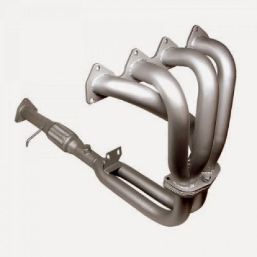
Acura Integra Header Installation Instructions


Acura Integra Header Installation Instructions - Parts List: 1 – Stainless Steel Header 1 – Oxygen Sensor Plug (for cars with oxygen sensor in catalytic converter) • Remove existing exhaust manifold and “A” pipe: Remove manifold, “A” pipe, and heat shields per factory service manual removal procedures. • Loosen bracket: Loosen the bracket indicated in the diagram to the right. This will allow easier alignment of the header to this bracket. • Install oxygen sensor: Install oxygen sensor into bung on collec- tor. Note: Some cars will have the oxygen sensor in the catalytic converter. In this case, install the supplied plug into the fitting on the header collector. • Install Comptech Header: Install header from bottom of car, line up all connections, and start all nut and bolt fasteners before final tightening to factory specifications. (torque header to cylinder head bolts/nuts to 23 lbs/ft) see diagram at right for other torque specs. • Wipe down header: Use a good solvent to remove any oil or contaminants on the header before starting engine. This will insure even discoloration (typical of stainless steel) of the header as it heats up. • Start engine: Start the engine and check for any exhaust leaks. After a few days of driving the car, recheck all con- nections for tightness.

Download : Acura Integra Header Installation Instructions

FORD F-SERIES TRUCK / SUV AUTOGUARD ANTITHEFT DEVICES

http://carmarzus.blogspot.com/
FORD F-SERIES TRUCK / SUV AUTOGUARD ANTITHEFT DEVICES PACKAGE CONTAINS: (1)-AUTOGUARD/FORD PART TOOLS REQURIED FOR INSTALLATION 8MM SOCKET TACK PULLER / SCREWDRIVER Installation Instructions : Step 1 With hood open, remove plastic core-support cover by locating and removing all two-piece plastic lock pins.

 (Some models do not have core-support) Step 2 Locate hood latch assembly anchor bolt on left side (passenger), Remove bolt Step 3 Locate hood latch assembly anchor bolt on right side Remove bolt. Step 4 Position AUTOGUARD over latch assembly aligning mounting holes with existing latch assembly holes. PLEASE NOTE: Ford uses a clip nut on the frame for securing the anchor bolt to the frame. Be careful when removing bolt, so clip will not fall off of frame. Step 5-a Insert Anchor bolt on left side hand tighten. Step 5-b Insert Anchor bolt on right side hand tighten.

Step 6 Tighten Anchor bolts, after you have aligned both sides. Step 7 Reinstall plastic core-support cover by locating and inserting all two-piece plastic lock pins. (Some models do not have core-support).

 Download : FORD F-SERIES TRUCK / SUV AUTOGUARD ANTITHEFT DEVICES

2008-2009 Buick LaCrosse BX1514 Installation Instructions

http://carmarzus.blogspot.com/
2008-2009 Buick LaCrosse BX1514 Installation Instructions -  Due to the design of the removable tabs, the RangeFinderII tow bar can not be used. Adapters, except the BX8833 and BX88151, can not be used with this baseplate. Installation Instructions: 1. Remove two push pins from the top of the plastic cover. Set cover and push pins aside to be reinstalled later. 2. Remove four push pins from the top of the fascia. Set push pins aside to be reinstalled later.

3. Remove the push pin from between the headlights. Do this to both sides of the vehicle. Set push pins aside to be reinstalled later. 4. Using the 7mm socket, remove two metric bolts from just inside wheel well in front of the tire on the edge of the fascia. Do this to both sides of the vehicle. Set bolts aside to be reinstalled later. 5. Using the 7mm socket, remove two metric bolts from underside of fascia, just forward of front tire. Do this to both sides of the vehicle. Set bolts aside to be reinstalled later. 6. Remove three push pins from bottom corner of fascia. Do this to both sides of the vehicle. Set push pins aside to be reinstalled later. 7. Just forward of the front tire push the wheel well cover aside, using the 10mm socket, loosen two metric bolts. Do this to both sides of the vehicle. Pull fascia forward to remove. Set bolts and fascia aside carefully to be reinstalled later. 8. Using the 10mm socket, remove three metric bolts from across the bottom of the belly pan underneath the bumper. Set bolts aside to be reinstalled later. 9. Remove two push pins from the belly pan extensions one on each side. Set push pins aside to be reinstalled later.

10. Just forward of the front tire, on the wheel well using the 7mm socket, remove two bolts. Pull forward on the center extension to remove the belly pan. Set belly pan and bolts aside to be reinstalled later. 11. On the passenger side, using the 10mm socket, remove one metric bolt from the horn bracket. Set the horn and bolt aside to be reinstalled later. 12. Using the reciprocating saw, mark and cut the bottom of the bumper bracket so that it is fl ush with the bottom of the frame rail. Do this to both sides of the vehicle.

Download : 2008-2009 Buick LaCrosse BX1514 Installation Instructions

2008-2009 FORD FOCUS ELECTRONIC CRUISE KIT 250-1840

http://carmarzus.blogspot.com/
2008-2009 FORD FOCUS ELECTRONIC CRUISE KIT 250-1840 - A. Pre-Installation Suggestions 1. It is advisable to disconnect the negative battery cable for 3 minutes before beginning installation, to avoid unintended air bag deployment. Note and record any anti-theft radio codes prior to disconnecting. Figure 1 2. Remove the driver side lower dash and kick panels. Remove the steering wheel shroud. Figure 2 B. Install Electronic Module 1. Apply the large supplied piece of double- sided adhesive tape to the Cruise Control Module. 2. Plug in the Main Wiring Harness, Switch Harness, and Pedal Interface Harness onto mating connectors of the Cruise Control Module.

Figure 3 3. Place the Cruise Control Module in the secure location behind the driver side dash area as shown in Figure 4 . 4. Route the Pedal Interface Harness through steering column and down to the accelerator. 5. Locate the 6 pin plug and mate connectors on the Pedal Interface Harness. Remove the accelerator 6-pin connector and apply to mating connector of Pedal Interface Harness. Apply the other connector to the accelerator. Figure 4 C. Wiring Connections 1. Locate the following wires to connect to the main harness from the control module: 2. Use the supplied self stripping connectors or T-tap to connect from the Main Harness to vehicle wire: 3. Apply the Black Ground Wire from the Main Harness to the Vehicle Ground Point at the kick panel. Figure 7 4. VSS : For reference, find the medal bracket in front of the gray and blue connectors at the center of the engine compartment.

Figure 8 . Locate the gray 2-pin or (3-pin manual transmission) connector on the transmission below the bracket. Figure 9. Note: The 3-pin connector will be covered with foil tape . Connect the Violet Wire from the Main Wiring Harness to the Blue extension wire using the male spade terminal (both supplied in hardware kit). Connect extension harness to Brown/Green Wire (VSS) of the connector. Apply the supplied weather sealant to the connection in the engine compartment. Be sure all of connection is sealed properly. Figure 10 5. Clutch Switch for Manual Transmissions : Locate the black 2-pin connector on the clutch switch. Connect the White Wire from the Main Wiring harness to the Green /Violet Wire of the clutch switch. Secure Cruise Control and Switch Interface Module harnesses with zip ties away from moving parts. Figure 11

Download : 2008-2009 FORD FOCUS ELECTRONIC CRUISE KIT 250-1840

1990-1993 Acura Integra Radio Replacement

http://carmarzus.blogspot.com/
1990-1993 Acura Integra Radio Replacement - Remove Factory Radio NOTE : To remove the Honda factory radio, (2) two screws at the rear of the radio must be removed from underneath the radio which can be accessed from behind the radio. The Honda radio is secured to the pocket below the radio and will pull out of the dash connected together as one unit. STEP 1 : Move to the passenger side of the vehicle. The screws that secure the radio/pocket assembly to the dash are at the rear of the radio.

The only way to access these screws is to look up at the rear of the radio from the passenger side of the vehicle. With an 8mm socket or phillips screw, locate and remove the screws as can be seen in the photos shown in the NOTE to the left. STEP 2 : Once the screws at the rear of the radio/ pocket assembly have been removed, the radio can be pulled forward out of the dash. Remove Factory Radio STEP 3 : Pull the radio out of the dash. Unplug the black cable plugged into the rear of the radio. Unplug the white plastic wire harness connector plugged into the rear of the radio. Completing The Radio Installation Move to: Wire New Radio Section Wiring The New Radio STEP 1 : Insert the radio installation kit into the dash until it snaps and secures to the dash. TIP: mount the kit to the opening in the dash BEFORE mounting the radio to the kit.

Mounting the radio to the kit before snapping the kit into the dash may prevent the kit from properly snapping into the dash. This step is shown in more detail in the “Mount New Radio” section. STEP 2 : Insert the new radio into the dash. Plug the black antenna cable into the rear of the new radio. Make sure all wire connections for the new radio have been completed and plug in any connectors for the new radio now. Slide the new radio into the radios mounting “cage” or mounting “sleeve”. The Installation Is Now Complete.
Download : 1990-1993 Acura Integra Radio Replacement

2003 HONDA ACURA RSX FOG LIGHTS INSTALLATION INSTRUCTIONS

https://www.blogger.com/blogger.g?blogID=305707988658003799#editor/target=post;postID=5637526110450761558
2003 HONDA ACURA RSX FOG LIGHTS INSTALLATION INSTRUCTIONS - PARTS LIST Right fog light Left fog light trim Right fog light trim Left bracket Right bracket Switch harness Fog light harness Switch Templates 4 Step screws 2 Washer-screws 4 Spring nuts Relay Washer-bolt Cushion tape 21 Wire ties. Wire tie with clip 2 Washers Left sub-bracket Right sub-bracket Fuse label TOOLS AND SUPPLIES REQUIRED Phillips screwdriver 10 mm Combination wrench Ratchet 10 mm Socket Diagonal cutters Drill 3 mm, 5 mm, and 10 mm Drill bits Hacksaw blade Utility knife Scissors Pushpin Masking tape Felt-tip pen.

INSTALLATION 1. Make sure you have the anti-theft code for the radio, then write down the frequencies for the preset buttons. 2. Disconnect the negative cable from the battery. Cutting the Front Bumper 3. Using scissors, cut out the templates. Fold both small templates as shown. 4. Position the large left template on the left bumper grille, and tape it in position using masking tape. 5. Using a pushpin, make a hole through each of the three marks indicated on the template. 6. Using a utility knife, score the bumper along the heavy line in the area shown. Remove the large template from the bumper. 7. Insert the two tabs of the small left template into the slits in the front bumper.

2003 HONDA ACURA RSX FOG LIGHTS

  Using a pushpin, make a hole through each of the two marks indicated on the template. 8. Remove the small template from the bumper. Using a 3 mm, 5 mm, and a 10 mm drill bit, drill a hole through each of the five marks. 9. Using a felt-tip pen, draw two straight lines across the two upper adjacent 10 mm holes you just made. Repeat on the lower pair of 10 mm holes. 10. Using a hacksaw or a utility knife, cut out the shaded areas for the fog light opening. 11. Position the right template on the right bumper grille, and repeat steps 5 through 10 to cut out the right fog light opening. 12. Disconnect the negative (-) and positive (+) cables from the battery, and release the clip from the holder bolt. Disconnect the negative (-) cable first.

Download : 2003 HONDA ACURA RSX FOG LIGHTS INSTALLATION INSTRUCTIONS

Jumat, 01 Mei 2015

Acura RSX Heated Mirror Installation Instructions

Acura RSX Heated Mirror Installation Instructions - Dissassembly: OK so let’s get started: It’s best if you have the Helms manual but you can do without it if you have done other similar installs on this or other cars. 2. Remove the door panel: a. You will need to remove the door handle assembly. Pop off the plastic cover behind the handle and you will find 2 screws.

Once you undo the screws you can pull the assembly out. Remove the lock cable from the door handle. b. Then unplug the connector. There is one more screw you will need to find once you remove the handle assembly. Remove this screw too. Every time I did this, the screw fell into the plastic door panel handle cavity so I had to retrieve this screw after the door panel came off by turning the panel upside down. Next remove the 2 screws under the armrest. c. Remove the black plastic trim piece on the inside of the door opposite the mirror. Roll the window down and pop the piece up and inward using a little upward pressure. A screwdriver taped so it would not mark or scratch anything works best. d. Now you are ready to remove the door panel.


To do this it is best to use a door trim tool. You can pick one up at your local auto store. This is used to remove the 8 clips that hold the plastic panel to the sheet metal. e. In order to completely remove the panel, unplug the connector for the window switch. 3. Remove the mirror assembly: Note it is possible to skip this step and work on the mirror while attached to the car a. Unscrew the three 8 mm nuts holding the mirror to the inside of the window. b. Unplug the mirror connector and take the mirror assembly totally off 4. Remove the glass mirror element from the assembly: a. Gently push the top of the mirror in as far as it will go. This will create a small space between the bottom of the mirror and the housing. Use mostly just your fingers for this.

 I also used a hair dryer and an assistant to heat the mirror (don’t over do it) while pulling the mirror with the black plastic holder from the white plastic actuator. I did use a screwdriver here very delicately to help separate the two items. This was easily accomplished without breaking the old mirror.

Download : Acura RSX Heated Mirror Installation Instructions

Rabu, 29 April 2015

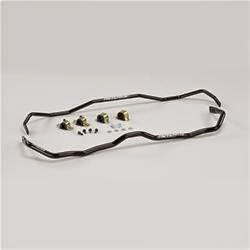
AUDI TT Sport Sway Bar Kit 22806

http://carmarzus.blogspot.com
AUDI TT Sport Sway Bar Kit 22806 - Installation of Hotchkis Front Sway Bar 1F Raising Vehicle Raise front of the vehicle by using a 4 post lift or drive-on ramps. Securely block the rear wheels of the vehicle. Do not remove the front wheels during installation for safety. 2F Observe Orientation Of the Bar Remove the lower splash shield, and observe the location and orientation of the front swaybar. 3F Remove End Links Locate and remove the lower end link nuts from both sides, and push links aside. 4F Remove Engine Mount Locate and remove lower engine mount that attaches to subframe.

The engine may want to shift forward which is ok. 5F Remove Exhaust Hanger Use a pry bar to remove the exhaust hanger located behind subframe. 6F Ride Height Sensor Locate the ride height sensor located on the drivers side lower control arm, and remove the nut from the stud that attaches the sensor to the arm. (Be careful, this part can break easily). 7F Sub Frame Support the sub frame with a jack, and locate and remove the 4 sub frame bolts that attach it to the chassis. Lower the jack until the sub frame is at full droop, and slightly pry down until you can access the sway bar bolts. (Don’t worry, it will not fall being that it is still attached to the struts.) 8F Remove the Sway Bar Now remove the sway bar brackets that attach it to the sub frame.

The drivers side bracket has a clamp for the power steering lines that must be removed in order to completely remove the bracket. (It does not need to be re-installed.) Now you can remove the sway bar. 9F Installation Place the new swaybar next to the factory bar so that you will be familier with the oriention that the bar is installed. Apply a good amount of the silicon grease that is supplied with the bushings, and install the bushings on the bar. After the swaybar is mounted the subframe, there is a line clamp bolted to the front of the rack & pinion on the passenger side that needs to be rotated 180 degrees in order to allow free articulation of the sway bar. Now the rest of the installation can be done in reverse order as the removal. You may need a jack to help place the subframe in the proper location.

Download : AUDI TT Sport Sway Bar Kit 22806

2007 Ford Focus Accessories List Guide

2007 Ford Focus Accessories List Guide - “Mobile-ease™” Hands Free System Connector Wiring Harness Required for Installation of “Mobile-ease™” Hands Free System 3W4Z-14A411-AA 2005-2007 Hands Free System Requires Connector Harness 14A411 for Installation3W4Z-19G399-AA2005-2007 “Street Appearance Package” ZX3/ZX5 Includes Front & Rear Bumper Fascia & Chromed Exhaust Tip, Primed 6S4Z-6120049-AA 2006-2007 ZX4 Includes Front & Rear Bumper Fascia & Chromed Exhaust Tip, Primed 6S4Z-5420049-BA 2006-2007 Bug Shield Styled Smoke-Color (Single-Pack) 5S4Z-16C900-A 2005-2007 Cargo Area Protector 3-Door/5-Door Black 1M5Z-6111600-AA 2001-2007 Sedan Black 1M5Z-5411600-DA 2001-2007 Wagon Black 1M5Z-7411600-CA 2001-2007 Cargo Logic System Without Logo Sedan, Heathered Black Ink (00) 3M5Z-5411600-AA 2003-2007 3-Door Hatchback, Heathered Black Ink (00) 3M5Z-6111600-AA 2003-2007 Wagon.

Heathered Pebble (65) 3M5Z-7411600-AA 2003-2007 Wagon, Heathered Flint (64) 3M5Z-7411600-BA 2003-2007 Wagon, Heathered Black Ink (00) 3M5Z-7411600-CA 2003-2007 Cargo Net, Retention 4-Door/Wagon Envelope Style YS4Z-54550A66-AA 2000-2007 Cargo Organizer 3-Door/5-Door/Sedan Black, For Use Without Subwoofer 5M5Z-54115A00-AAA 2005-2007 Cargo Organizer, Interior Wagon Black, With Ford Logo F8CZ-54115A00-BAA 2000-2007 Cargo Security Shade For Wagon, Med. Light Flint 5S4Z-7445440-BAA 2005-2007 Med. Light Pebble 5S4Z-7445440-BAB 2005-2007 Cover, Front End Full, Black 5S4Z-19A413-AA 2005-2007 Deflectors, Side Window 3-Door 2-Piece Set, Smoke-Color YS4Z-18246-AA 2001-2007 2-Piece Set, Smoke-Color (Bulk Pack of 10) YS4Z-18246-BA 2001-2007 2-Piece Set, Smoke-Color (Bulk Pack of 25) YS4Z-18246-CA 2001-2007 2-Piece Set, Smoke-Color (Bulk Pack of 50) YS4Z-18246-DA 2001-2007 Sedan/5-Door 4-Piece Set, Smoke-Color YS4Z-18246-EA 2001-2007 4-Piece Set, Smoke-Color (Bulk Pack of 10) YS4Z-18246-FA 2001-2007 4-Piece Set, Smoke-Color (Bulk Pack of 25) YS4Z-18246-GA 2001-2007 4-Piece Set, Smoke-Color (Bulk Pack of 50) YS4Z-18246-HA 2001-2007 Wagon 4-Piece Set, Smoke-Color YS4Z-18246-JA 2001-2007 4-Piece Set.

 Smoke-Color (Bulk Pack of 10) YS4Z-18246-KA 2001-2007 4-Piece Set, Smoke-Color (Bulk Pack of 25) YS4Z-18246-LA 2001-2007 4-Piece Set, Smoke-Color (Bulk Pack of 50) YS4Z-18246-MA 2001-2007 Floor Mats, All Weather Molded Vinyl Front & Rear, 4-Piece Set, With Focus Logo Ebony 6S4Z-5413300-A 2001-2007 Med. Dk. Flint 6S4Z-5413300-B 2001-2007 Med. Dk. Pebble 6S4Z-5413300-C 2001-2007 Floor Mats, Carpeted Front & Rear, 4-Piece Set, With Vehicle Logo Ebony 4M5Z-5413300-AA 2005-2007 Med. Dk. Flint 4M5Z-5413300-AC 2005-2007 Med. Dk. Pebble 4M5Z-5413300-AD 2005-2007 Lights, Fog Original Equipment 5S4Z-15200-AA 2005-2007 Lock Kit, Wheel Anti-Theft Chrome Plated For Exposed Lugs, Includes (4) Lock Lugs and (1) Key

Ford Explorer Sport Trac Advanced Folding X5 Supra Cover INSTALLATION INSTRUCTIONS

Ford Explorer Sport Trac Advanced Folding X5 Supra Cover INSTALLATION INSTRUCTIONS - Advanced Folding X5 Supra Cover 2001-2006 Ford Explorer Sport Trac 2007-2010 Ford Explorer Sport Trac (Part Number’s 28570 & 28572). Suggested Tools Installation Kit â Scissors â 5/16″ Socket or Wrench â 3/8″ Wrench â Ratchet â Hammer â Chisel or knife â 1/8″ Punch or Nail â #1 Phillips Screwdriver â 4 Latch Catches for 28570 â 2 3rdLeg Hinge Brackets for 28570 â 12 Washers â 12 Latch Catch Screws â 2 D-Seals â 2 Nuts and 2 Bolts â Latch Catch Screws.

Removing Plastic Plugs 1. Cut off 8 plastic plugs (2 in each corner) with a chisel or knife and push the remaining pieces through the hole using a hammer and nail or punch. Make sure holes are clear. (Fig. 1). 2. Pry 4 plugs out (with a standard screwdriver) of the center of the sides of the truck box (2 each side). (Fig. 2). rail D seal at end of Tailgate Box Seal The torque screws located in the middle of the sides need to be removed according to the instructions. DO NOT REMOVE BOTH SCREWS AT THE SAME TIME. The bracket behind the side wall will fail. Attaching Latch Catch and Keyhole Brackets 3. Place lock washers on screws (12x). (Fig. 3). 4. Place (12) screws with lock washers on, (4) Latch catch brackets (#ST101), and (2) Keyhole brackets (#ST102) into the bed of the truck. (Fig. 4). Mounting Keyhole Bracket 5. Remove lower screw (only the lower screw) using a 30# Torque bit with ratchet. 5. Remove 1 side screw (only the 1 side screw).

6. Place one screw through the lower slot in the keyhole bracket and hand thread into hole where you just removed the torque screw. Then tighten with Phillips screwdriver. 7. After tightening the lower screw, remove upper screw. Then hand thread another screw through the upper slot of the keyhole bracket and into the upper hole where you just removed the torque screw.

Download : Ford Explorer Sport Trac Advanced Folding X5 Supra Cover INSTALLATION INSTRUCTIONS

2004-2005 FORD FOCUS COLD AIR INTAKE SYSTEM PART NUMBER: 21-452 INSTALLATION INSTRUCTIONS

http://www.aemintakes.com/instructions/AEM-21-452_inst.pdf
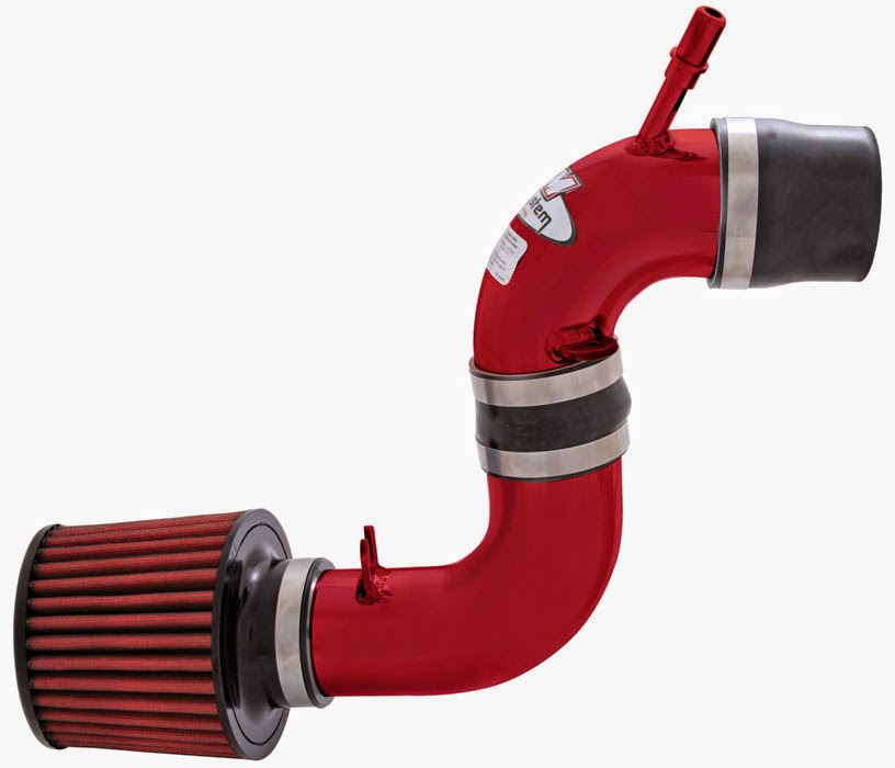
2004-2005 FORD FOCUS COLD AIR INTAKE SYSTEM PART NUMBER: 21-452 INSTALLATION INSTRUCTIONS - Read and understand these instructions BEFORE attempting to install this product. Failure to follow installation instructions and not using the provided hardware may damage the intercooler system, throttle body and engine. 1. Preparing Vehicle a. Make sure vehicle is parked on level surface. b. Set parking brake. c. If engine has run in the past two hours, let it cool down. d. Disconnect negative battery terminal. e. Raise the front of the vehicle with a jack. Refer to your owner’s manual for proper jack and jack stand placement to properly support vehicle.

Support your vehicle using properly rated jack stands before wheel removal or while working under the vehicle. NEVER WORK UNDER A VEHICLE WITHOUT USING JACK STANDS. i. Remove the driver side wheel. f. Do not discard stock components after removal of the factory system. 2. Removal of stock system d. Remove the upper air box and the bolt in the frame rail. Release the metal clamp from the Mass Air Flow (MAF) sensor housing. c. Loosen the two bolts that secure the upper air box. a. Factory air box system installed. b. Release the fitting on the inlet pipe nipple. Loosen the hose clamp at the throttle body. e. Unplug the MAF sensor. Loosen hose clamp at the bottom of the MAF housing. f. Remove the MAF housing. Confirm that the air straightener is still attached to the lower opening. g. From underneath the vehicle, remove the two screws that secure the splash shield. h. Pull the air snorkel from the splash shield and remove the splash shield. i. Remove the two screws at the upper rear section of the lower air box. j. Remove the screw at the upper front section of the lower air box. Remove the lower air box. 3. Installation of AEM® Intake System a.

When installing the intake system, do not completely tighten the hose clamps or mounting hardware until instructed to do so. b. Place the rubber reducer and hose clamps onto the throttle body. c. Secure the upper inlet pipe to MAF housing with the supplied bolts. d. Place the silicone reducer onto the MAF housing. e. Install the upper pipe onto the throttle body. Attach the breather hose to nipple on the intake pipe.

Download : 2004-2005 FORD FOCUS COLD AIR INTAKE SYSTEM PART NUMBER: 21-452 INSTALLATION INSTRUCTIONS

1997 Jeep Cherokee Serpentine Belt INSPECTION ADJUSTMENT REMOVAL & INSTALLATION

http://ww2.justanswer.com/uploads/JHoop/2010-08-15_191723_1.pdf
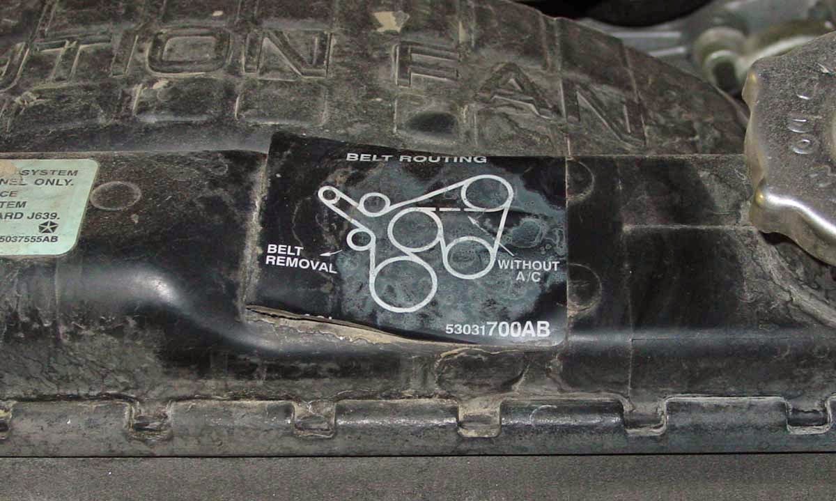
1997 Jeep Cherokee Serpentine Belt INSPECTION ADJUSTMENT REMOVAL & INSTALLATION - 1997 Jeep Cherokee 2WD 4.0L MFI 6cyl | Repair Guides. eep Wagoneer/Command o/Cherokee 1984-1998 Serpentine Belt INSPECTION ADJUSTMENT REMOVAL & INSTALLATION INSPECTION When inspecting serpentine drive belts, small cracks that run across the ribbed surface of the belt from rib to rib are considered normal.

If the the cracks are running along the rib (rather across), this is not normal and the belt(s) must be replaced. ADJUSTMENT It is not necessary to adjust belt tension on the 5.2L or 5.9L engines and on the 2.5L and 4.0L engines (without power steering). These engines are equipped with an automatic tensioner. The tensioner maintains correct tension at all times. 2.5L and 4.0L Engines With Power Steering See Figures 1, 2, 3 and 4 If the vehicle is not equipped with power steering, it will be equipped with an idler pulley. If equipped with an idler pulley, refer to and follow the 5.2L/5.9L belt removal and installation procedure. Loosen the pump upper pivot bolt, lower locknut and pump adjusting bolt using a ratchet and 13mm socket or a 13mm box wrench.

1. Use a belt tension gauge placed in the middle of the belt being tested. Proper tension for a new belt is 180-200 lbs. (800-900 N) and 140-160 lbs. (623-712 N) for a used belt. 2. Tighten the pump adjusting bolt to achieve proper tension and recheck the belt tension. 3. Removal & Installation 2.5L and 4.0L Engines With Power Steering 1. Loosen the pump upper pivot bolt, lower locknut and the pump adjusting bolt using a ratchet and 13mm socket or a 13mm box wrench. 2. Remove the belt. 3. To install: Install the belt. 4. Tighten the pump adjusting bolt to achieve proper tension. 5. Install the pump rear mounting bolts, pivot bolt and locknut. Tighten the bolts to 20. ft. lbs. (27 Nm). 6. Check the belt for proper tension. If tension is incorrect, refer to the adjustment procedure in this section. 7.

Download : 1997 Jeep Cherokee Serpentine Belt INSPECTION ADJUSTMENT REMOVAL & INSTALLATION

Selasa, 28 April 2015

2000 Ford Pickup F250 Super Duty EXHAUST BACKPRESSURE (EBP) SENSOR

carmarzus.blogspot.com
2000 Ford Pickup F250 Super Duty EXHAUST BACKPRESSURE (EBP) SENSOR -
SELF-DIAGNOSTICS – EEC-V (DIESEL) -2000 Ford Pickup F250 Super Duty EXHAUST BACKPRESSURE (EBP) SENSOR. Perform this test when directed by QUICK TEST. This test is intended to diagnose: Exhaust Backpressure (EBP) Sensor • Wiring Harness Circuits (SIG RTN, VREF & EBP Signal) • Powertrain Control Module (PCM) • 1) DTC P0470 This DTC indicates PCM detected EBP sensor malfunction during KOEO ON-DEMAND SELF-TEST. Possible causes for this DTC are: Faulty EBP Sensor • Open Or Shorted Circuit • Faulty PCM • Ensure scan tool is connected to Data Link Connector (DLC). Using scan tool, select EBP PID from PID/DATA monitor menu. If EBP reading is less than 18.5 psi, clear DTCs. Repeat KOEO ON-DEMAND SELF-TEST . If DTC is still present, replace PCM. If EBP reading is 18.5 psi or more, go to next step. 2) Check Signal Ground Circuit Turn ignition off.

Disconnect EBP sensor connector. Sensor is located on top front of engine. Inspect for damaged pins, corrosion and loose wires. Repair as necessary. Measure resistance between ground and Gray/Red wire at EBP sensor wiring harness connector. See Fig. 11 . If resistance is less than 5 ohms, replace EBP sensor. If resistance is 5 ohms or more, locate and repair open circuit in Gray/Red wire. 3) Continuous DTC P0470 This DTC indicates PCM detected a EBP sensor malfunction during normal driving conditions. Possible causes for this DTC are: Faulty EBP Sensor • Faulty Connection • Faulty PCM • Ensure scan tool is connected to Data Link Connector (DLC). Using scan tool, select EBP PID from PID/DATA monitor menu. While observing EBP PID, wiggle and bend small sections of wiring harness starting at EBP sensor connector and working toward PCM. If EBP reading fluctuates, isolate fault and repair as necessary.

If reading does not fluctuate, go to next step. 4) Check Connector Disconnect EBP sensor connector. Sensor is located on top front of engine. Disconnect PCM 104-pin connector. Inspect connectors for damaged pins, corrosion and loose wires. Repair as necessary. Clear DTCs and repeat QUICK TEST . If both connectors are okay, no problem is indicted at this time. 5) DTC P0471 This DTC indicates PCM detected an EBP sensor malfunction during normal driving conditions and with EBP sensor enabled. Possible causes for this DTC are: Faulty EBP Sensor. • Plugged Or Restricted Sensor Supply Tube • Damaged Exhaust Pressure Regulator (EPR) Linkage Or Butterfly Damage • Faulty PCM • Perform KOER ON-DEMAND SELF-TEST . If any DTCs are present, repair fault(s) before continuing with this test. Using scan tool, select EBP PID from PID/DATA monitor menu. Road test vehicle performing hard accelerations while monitoring EBP PID. If EBP reading increases to more than 25 psi with EBP sensor on, no problem is indicated at this time. If EBP reading does not increase to more than 25 psi, go to next step.
Download :  2000 Ford Pickup F250 Super Duty EXHAUST BACKPRESSURE (EBP) SENSOR

Popular Posts

Twitter Facebook More

 
Design by Free WordPress Themes | Bloggerized by Lasantha - Premium Blogger Themes | Affiliate Network Reviews